


GB
- 31 -
supply is restored. For the equipment to run,
the switch must be turned off and then on
again.
Both guards have the same assembly/
adjustment method.
Adjust the guard (4) to protect your hands
so that the material being ground is
directed away from your body.
The position of the guard (4) can be
adjusted to any specific working conditions.
Undo the clamp handle (a) and turn the
guard (4) into the required position.
Ensure that the guard (4) correctly covers
the gear wheel casing. The closed side of
the protective guard must always point
toward the operator.
Secure the clamp handle (a) again.
Ensure that the guard (4) is secure.
Take care that the safety device is secure.
Never use the angle grinder without the
guard.
6.3 Test run for new grinding or cutting
Wheels
Allow the angle grinder to run in idle for at
least 1 minute with the grinding or cutting
wheel fitted in place. Vibrating wheels are to
be replaced immediately.
Simple wheel change by spindle lock (1).
Press the spindle lock (1) and allow the
grinding wheel to latch in place.
Open the flange nut with the flange nut
wrench. (Fig. 6)
Change the grinding or cutting wheel and
tighten the flange nut with the flange nut
wrench.
Wait until the machine has reached its
top speed. You can then position the angle
grinder on the workpiece and machine it.
7.2 Changing the grinding or cutting
wheels (Fig. 5 / 6)
Use the flange nut wrench (5) supplied to
change the grinding or cutting wheels. The
flange nut wrench (5) is stored in the additi-
onal handle (3). Pull the flange nut wrench
(5) out of the additional handle (3) when you
need it.
Important!
For safety reasons, the angle
grinder must not be operated with the flange
nut wrench (5) inserted in it.
Warning! Pull out the power plug.
7. Operation
7.1 Switch (Fig. 4)
The angle grinder comes with a safety switch
which is designed to prevent accidents. To
switch on, depress the rear position of the
ON/OFF switch (2) and the push forward. To
switch off the angle grinder, depress the
ON/OFF switch (2) at the back. The ON/OFF
switch (2) will jump back into its starting
position.
Restart safeguard
If the mains power supply is interrupted when
the switch is locked in the On position, the
electric tool will not run after the power
For grinding or cutting wheels up to approx.
3 mm thick, screw on the flange nut with the
flat side facing the grinding or cutting wheel.
7.3 Flange arrangements when using
grinding wheels and cutting wheels
(Fig.7-10)
Notice!
Only ever press the spindle lock when the
motor and grinding spindle are at a stand-
still! You must keep the spindle lock pressed
while you change the wheel!
Содержание 165770.01
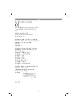
Страница 2: ...2 FIG 1 2 1 3 5 4a 4b...
Страница 3: ...3 FIG 2 B A 3 4 a 2 3 5 FIG 3 FIG 4 FIG 5 FIG 6...
Страница 4: ...4 a b FIG 7 FIG 8 1 4 a b a b a b FIG 9 FIG 10 FIG 11 FIG 12 30 40...


