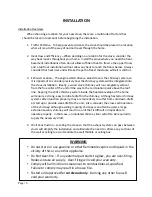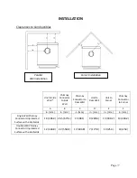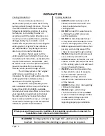
Page | 13
2.
0
ft.
18.
0
in.
3.
0
ft.
INSTALLATION
Approved
Venting
Method
3:
Internal
or
External
Masonry
Chimney
System
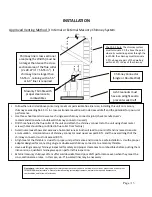
10
ft.
Chimney
liner
cross
‐
sectional
area
(Length
x
Width)
must
be
no
larger
than
twice
the
cross
‐
sectional
area
of
the
flue
collar
(2
x
28.27
in
2
=
56.55
in
2
).
If
chimney
liner
is
larger
than
56.55
in
2
,
relining
with
a
5.5”
or
6.0”
liner
is
required
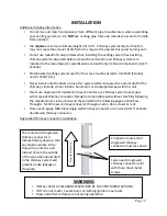
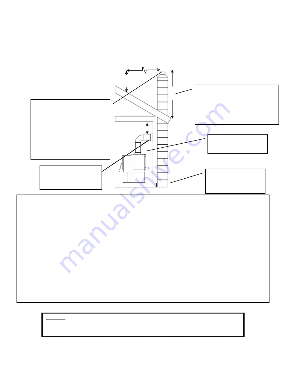
The
10
‐
3
‐
2
Rule:
The
chimney
system
must
terminate
3.0
ft.
above
the
point
where
its
centerline
passes
through
the
roof
AND
the
chimney
must
terminate
2.0
ft.
above
any
part
of
the
dwelling
within
a
10
ft.
radius
of
the
chimney.
Chimney
Connector
(Single
or
Double
Wall)
Masonry
Thimble
with
proper
clearance
to
combustibles
Ash
Cleanouts
must
have
an
airtight
seal
to
prevent
weak
draft.
•
Follow
the
rules
listed
above
concerning
maximum
permissible
flue
liner
size;
installing
this
unit
on
masonry
chimneys
exceeding
56.55
in
2
in
cross
‐
sectional
area
will
result
in
decreased
draft
and
the
potential
for
poor
unit
performance.
•
Use
three
sheet
metal
screws
at
each
single
wall
chimney
connector
joint
(check
manufacturer’s
recommendations
when
double
wall
chimney
connector
is
used).
•
Drill
three
holes
in
the
flue
collar
of
the
unit
and
attach
the
chimney
connector
to
the
unit
using
sheet
metal
screws
(holes
should
be
pre
‐
drilled
in
flue
collar
from
factory).
•
Avoid
numerous
elbows
and
excessive
horizontal
runs
as
both
will
lead
to
poor
draft
and
increased
creosote
accumulation.
Horizontal
runs
of
chimney
connector
must
never
exceed
4.0
ft.
and
the
overall
length
of
the
chimney
connector
must
not
exceed
8.0
ft.
•
A
tight
seal
at
the
thimble
is
crucial
for
proper
unit
performance
and
to
create
a
safe
installation.
Use
the
proper
adapter
designed
for
connecting
single
or
double
wall
chimney
connector
to
a
masonry
thimble.
•
Have
existing
masonry
chimneys
inspected
for
safety
and
proper
clearances
to
combustibles
before
putting
them
into
service;
a
qualified
chimney
sweep
can
perform
this
inspection.
•
External
masonry
chimneys
often
suffer
cold
downdrafts
and
poor
draft
performance
even
when
they
meet
the
cross
‐
sectional
area
rules.
In
this
case,
a
6.0”
insulated
liner
may
be
necessary.
Please
Note:
Installation
diagrams
are
for
reference
purposes
only
and
are
not
drawn
to
scale,
nor
meant
to
be
used
as
plans
for
each
individual
installation.
Please
follow
all
venting
system
requirements,
maintain
the
required
clearances
to
combustibles,
and
follow
all
local
codes.
Содержание Smartstove 15-SSW02
Страница 33: ...Page 33 ILLUSTRATED PARTS DIAGRAM 16 ...


