5.2 How to power the module
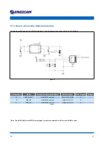
Read carefully the related sections before starting the power stage design. This module needs to be supplied with a +3.3Vin power.
Refer to the table below for the power supply range specification. The power dissipated by the module in the operating mode is about
200 mA, but
the system must provide at least a power of 1A at 3.3V to allow the start of the module.
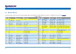
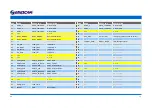
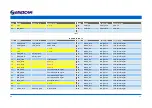
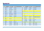
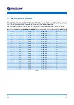
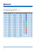
In the following table are shown the module power supply pins numbering. Connect all power supply pins in order to avoid damage.
A connector
B connector
Name
Primary Function Description
GPIO Capable
Voltage
19
-
+3,3V
Power PIN
N
-
20
-
+3,3V
Power PIN
N
-
21
-
+3,3V
Power PIN
N
-
22
-
+3,3V
Power PIN
N
-
1
5
GND
Power PIN
N
-
11
7
GND
Power PIN
N
-
16
31
GND
Power PIN
N
-
32
46
GND
Power PIN
N
-
44
48
GND
Power PIN
N
-
45
54
GND
Power PIN
N
-
61
58
GND
Power PIN
N
-
63
60
GND
Power PIN
N
-
68
63
GND
Power PIN
N
-
72
65
GND
Power PIN
N
-
79
66
GND
Power PIN
N
-
87
69
GND
Power PIN
N
-
-
71
GND
Power PIN
N
-
-
76
GND
Power PIN
N
-
-
89
GND
Power PIN
N
-
-
90
GND
Power PIN
N
-
Table 6
D N :
2 1

