11a/b/g Wireless Multi-Client Bridge/AP/WDS
Version 1.0
9
2 Understanding the Hardware
2.1 Hardware Installation
1. Place the unit in an appropriate place after conducting a site survey.
2. Plug one end of the Ethernet cable into the RJ-45 port of the device and another
end into your PC/Notebook.
3. Insert the DC-inlet of the power adapter into the port labeled “DC-IN” and the
other end into the power socket on the wall.
This diagram depicts the hardware configuration
2.2 IP Address Configuration
This device can be configured as a Bridge/Router or Access Point. The default IP
address of the device is
192.168.1.1 (Client Bridge mode)
,
192.168.1.2 (Access
Point mode)
. In order to log into this device, you must first configure the TCP/IP
settings of your PC/Notebook.
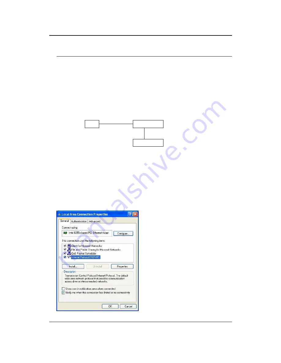
1. In the control panel, double click Network Connections and then double click on
the connection of your Network Interface Card (NIC). You will then see the
following screen.
Bridge/AP
PC
Power Outlet
Ethernet
AC/DC cable


