


Integrated Synchronous Servo Drives
HFI 22xx / HFI 26xx / HFI 32xx / HFI 37xx
Technical Data - System Data HFI26xx
Operating Manual Rev. 1.3
www.engelantriebe.de
Page 11
6.3
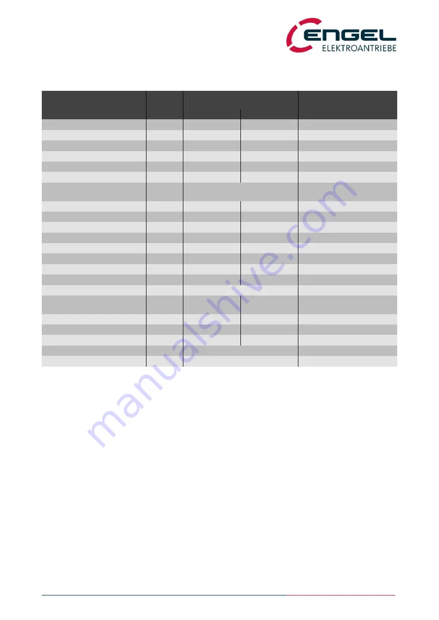
System Data HFI26xx
Designation
Unit
Value
additional information
HFI2630
HFI2660
Rated speed
min
-1
4000
3000
Peak speed
min
-1
5000
4000
Rated input current
*1)
ADC
8.8 / 4.4
10.6 / 5.3
24V-Type/48V-Type
Rated motor current
*2)
A
spk
13.2 / 6.8
17.9 / 8.9
24V-Type/48V-Type
Peak motor current
*2)
A
spk
26.5 / 13.7
37.5 / 18.5
24V-Type/48V-Type
Motor current measurement
range
A
55.0 / 27.5
Rated power
*3)
W
150
190
Rated torque
*3)
Nm
0.36
0.61
Peak torque
Nm
0.75
1.30
Torque constant
Nm/A
0.030 / 0.058
0.036 / 0.073
24V-Type/48V-Type
Voltage constant
V/1kmin
-1
3.6 / 7.0
4.4 / 8.8
24V-Type/48V-Type
Flange dimension
mm²
55 x 55
Drive length (without fieldbus
module)
*4)
mm
136 / 166
166 / 196
without/with parking brake
Weight
kg
1.2 / 1.45
1.6 / 1.85
without/with parking brake
Parking Brake (optional):
automatically operated
Static braking torque
Nm
2.0
Power (electric)
W
10
*1) The rated input current is the direct current drawn in nominal operation (rated torque at rated speed) from the input
voltage (24 VDC or 48 VDC). The current drawn from the input voltage is proportional to the converted power, not to
be confused with the torque-building motor current, which is displayed as sine peak value in DSerV and is propor-
tional to the motor torque.
Please also observe that the supply line is lossy. This leads to a reduction in voltage and speed at the motor system
and to increased power consumption of the device. A connection line with a nominal cross-section of 1.5 mm² al-
ready has an overall loss resistance of approx. 2 x 12.5 mΩ/m (conductors and return conductors)! Appropriate pow-
er reserves must be provided in the supply!
*2) Motor phase current as a sine peak value, which is required for the generation of the rated or peak torque. Motor
phase current is displayed in DSerV. Not to be confused with the current taken from the supply.
*3) The specified values apply for the installation of the drive on a system surface made of aluminium (A = 0.1 m²,
d = 10 mm). It must be taken into consideration that the specified continuous output power must be derated for
thermally unfavourable couplings.
*4) With fieldbus module the length of the drive increases by 14 mm.


