Integrated Synchronous Servo Drives
HBI 22xx / HBI 26xx / HBI 32xx / HBI 37xx
Operating Manual Rev. 1.6
www.engelantriebe.de
page 13
4.1
Speed control operating mode
The adjustment of the speed setpoint takes place through one of three setpoint sources:
Analogue input AI1 (differential input for voltage setpoint
10V, cw and ccw rotation)
RS232 (through DSerV service software under menu
SETPOINT RS232
)
Two fixed speeds
(
constant values
)
defined as relative amounts for the value
Setpoint scaling
.
Digital input DI6 dynamically selects between the two constant values 1 / 2. (see chapter
The control enable always takes place through digital input DI1 (+15... +30V
enable).
Note:
Prior to the adjustment and/or operation of the speed controller, it must be ensured that the
current limits and control parameters of the current controller are correctly set. The opti-
misation of current and speed controllers is described in chapter 9 Controller optimisation.
Sin² ramp not possible with analogue speed specification!
For
the
function
and
influence
of
the
digital
inputs
DI2,
DI3,
see chapter 4.4.2 Digital inputs.
The setting of the parameter
Polarity
(
see chapter
also takes effect in speed control operating mode.
In the menu
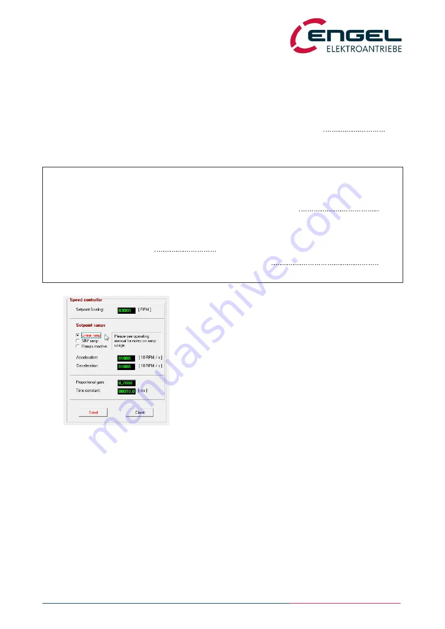
OPTIMISATION / SPEED CONTROLLER
the
parameters of the speed controller are set.
Setpoint scaling:
Target velocity for a setpoint value of 100% through
-
analogue input or
-
constant values or
-
RS232 setpoint.
Setpoint ramps:
Acceleration and deceleration ramp of the speed setpoint.
The input values correspond to the CAN objects
profile acceleration
and
profile
deceleration
and apply for the operating modes with subordinate speed control.
The object
motion profile type
contains the selected ramp characteristics
(linear / sin² / inactive).
Linear ramp:
A setpoint step-change is limited to a fixed rate of change (slope) which can be
parameterised.
Unit: [10 RPM / sec]


