


21
C048-725-30 Rev. B (01/2020)
6.0
6.0 Operation
Operation
(Models with LED Display)
(Models with LED Display)
6.1
6.1 Layout and Function of Logic PCB Interface
Layout and Function of Logic PCB Interface
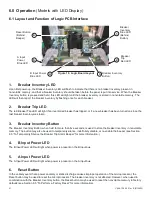
1.
Breaker Inventory LED
Upon first power-up, the Breaker Inventory LED will flash to indicate that there is no breaker inventory present in
nonvolatile memory, and that a breaker inventory should be taken before the panel is put into service� When the Breaker
Inventory button is pressed and held, this LED will light until the breaker inventory is stored in nonvolatile memory� The
LED will then report the breaker inventory by flashing once for each breaker.
2.
Breaker Trip LED
The red Breaker Trip LED will light if an inventoried breaker has tripped, or if a new breaker has been turned on since the
last breaker inventory was taken�
3.
Breaker Inventory Button
The Breaker Inventory Button, when held for more than five seconds, is used to store the breaker inventory in nonvolatile
memory. The button may also be used to temporarily silence, indefinitely disable, or re-enable the beeper
(see Section
6�3 “To Temporarily Silence the Breaker Trip Alarm Beeper” for more information� )�
4.
B Input Power LED
The B Input Power LED will light when power is present on the B input bus�
5.
A Input Power LED
The A Input Power LED will light when power is present on the A input bus�
6.
Reset Button
In the unlikely event that a power anomaly or static discharge causes improper operation of the microprocessor, the
Reset button may be used to reset the microprocessor. The breaker inventory is not affected. However, when used in
combination with the Breaker Inventory button, the Reset button may be used to reset the nonvolatile memory to factory
defaults (see Section 6�5 “To Perform a Factory Reset” for more information)�
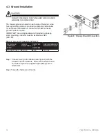
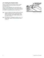
Figure 18. Logic Board Layout
1
Breaker
Inventory
Blue LED
(Behind
Button)
2
Breaker
Trip
Red LED
3
Breaker Inventory
Button
4
B Input Power
Blue LED
5
A Input
Power
Blue LED
6
Reset Button
(Behind
Beeper)
Содержание alpha Matrix C16
Страница 31: ......


