


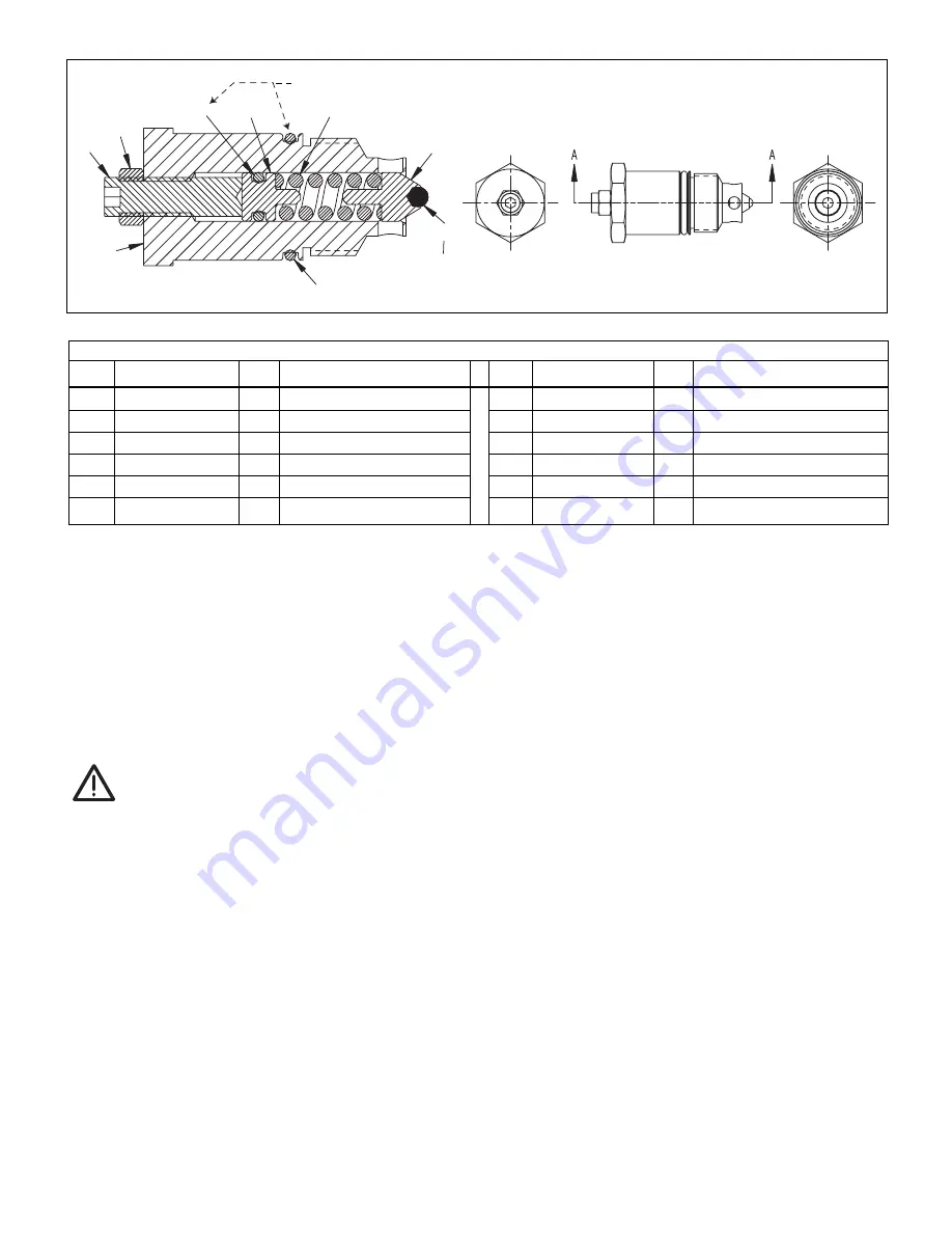
5
1
★
DC5138190
1
Body
2
★
BC2514027F
1
Set Screw
3
★
B1003503
1
O-Ring
4
★
DC5127007
1
Plug
5
★
A8126110
1
Spring
6
★
DC5125013
1
Guide
7
★
B1003016
1 1/8 Dia. Ball
8
★
B1223503
1 O-Ring
9
★
B1001123
1 Nut
★
DC5124290
1
Seat
(not shown) (See Fig. 3)
★
P20037 1
Gasket
(not shown) (See Fig. 3)
Repair Parts List for Figure 6, User Adjustable Relief Valve Assembly
Item Part Number
Qty.
Description
Item
Part Number
Qty. Description
1
8
2
9
3
4
5
6
7
Grease before assembly.
Figure 6, User Adjustable Relief Valve Assembly
TROUBLE SHOOTING AND REPAIR OF VE32 AND VE32D ELECTRIC VALVES
In diagnosing malfunctioning valves, certain symptoms
may be common not only to valves, but often to hydraulic
equipment in general. Before repairing the valve, mount
a different VM32 onto the pump and verify that the
problem is not with the pump.
TROUBLESHOOTING:
CAUTION:
Standard safety procedures are to be followed
during assembly to minimize any possibility of
injury.
1. Inability to obtain any pressure may be the result
of damaged connector seals on the pump, or failed
relief valve components (items 6,7 figure 6), or a
damaged check valve (item 3, figure 5C), or an
indication that the valve stack (item 1, figure 5C)
needs to be rebuilt. These problems are usually a
symptom of contaminated hydraulic oil. The system
should be drained and refilled with fresh ENERPAC
hydraulic oil.
2. Pressure leaks that are consistent and increase
proportionately with increasing pressure ranges are
usually the result of leaking gaskets or threaded
surfaces such as NTPF fittings or plugs.
3. Ball seat leakage is often erratic and intermittent and
is caused by contaminants trapped on the sealing
edge. Over time, as wear occurs, the check valve
and the valve stack (item 1, figure 5C) will need to be
replaced.
4. Leakage observed on the external surfaces is an
indication that the oring (item 13, figure 2, item 4,
figure 5C) and o-ring (item 6, figure 6) needs to be
replaced.
DISASSEMBLY:
1. Remove the 4 socket head cap screws and remove
the valve from the pump (item 76,figure 4A).
2. Remove the return tube (item 75) and gasket (item
70,figure 4A).
3. Remove the 4 socket head cap screws (item 3, figure
5A) and remove the poppet valve assembly.
4. Inspect the 3 o-rings (item 13, figure 2, item 4, figure
5C) for damage such as nicks, cuts, extrusion of
material. Replace if necessary.
5. Remove set screw (item 9, figure 2).
6. Remove valve plug (item 3, figure 2).
7. Remove solenoid stem (item 6, figure 2).
8. Remove valve stack (items 1A thru 1H, figure 2).
9. Inspect o-rings and glyd spring for damage such as
nicks or cuts. Replace if necessary.
10. The poppet valve stack (item 1G, figure 2) is a
matched subassembly. This part is only available as
a pre-assembled component.
11. Inspect the bore in the body (item 2, figure 2) for
Press Item 7 into Item 6 to 100 psi using a 10-ton press. Insert guide
and ball onto end of AT-0325c to help hold in place during pressing.
★
Indicates items included in and available only as a part of Repair Kit DC5139900SR.
Содержание VE32
Страница 26: ...VE32 VE32D VE32N LOMAR FT 1380 3 1 L2612 Rev D 03 10 26...
Страница 27: ...27...
Страница 28: ...VE32 VE32D VE32N LOMAR FT 1380 3 1 L2612 Rev D 03 10 28...
Страница 29: ...29...
Страница 30: ......
Страница 31: ......


