


L4213_h
7
The pump must also be equipped with a separate safety
pressure relief valve that opens if the system working
pressure exceeds 10,150 psi [700 bar]. Verify that the
pump safety relief valve is adjusted to the proper setting
before using the pump with the cylinder(s).
4.2 Hydraulic Oil Requirements
Use of Enerpac HF Series ISO 32 hydraulic oil is
recommended. Enerpac HF oil is available at your local
Enerpac Distributor or Authorized Service Center.
NOTICE
• Failure to use the correct oil type (high-quality ISO
32 hydraulic oil) may result in damage to cylinder
hydraulic components and will void the product
warranty.
• Be sure that the oil is clean. The oil cleanliness
should be maintained to a maximum level of
18/16/13 per the ISO4406 standard. If the oil
develops a milky, cloudy or dark appearance, it
should be changed immediately.
• To avoid overfilling and possible equipment
damage, add oil to the pump reservoir only after
all cylinder plungers are completely retracted and
system pressure is released.
• When using a hand-operated pump to power the
cylinder(s), it is permissible to use a high-quality
brand of ISO 15 hydraulic oil. The lower oil viscosity
will result in reduced pumping effort, especially in
cold weather conditions.
4.3 Hydraulic Connections
A single hydraulic coupler provides hydraulic flow
for both advance and retract functions. The coupler
is compatible with all Enerpac HCB Series hydraulic
hoses.
The coupler size varies depending on cylinder model:
• Models CULP10 through CULP50 are equipped
with one 1/4”-18 NPTF female coupler (Enerpac
AH630).
• Model CULP100 is equipped with one 3/8”-18
NPTF female coupler (Enerpac CR400).
Be certain that all couplers are fully connected, so that
hydraulic flow is not blocked or restricted.
All hoses, fittings and other hydraulic components in the
circuit must be rated for at least 10,150 psi [700 bar]
operation.
4.4 Air Removal
Trapped air must be removed from the hydraulic cylinder
and hose before placing the system into operation. If
multiple cylinders are to be used, it is recommended
that air be removed from each cylinder individually.
Refer to the following procedure:
1. Place the cylinder in the vertical position, on a
flat surface. Be sure that there is no load on the
plunger.
2. Position the hydraulic pump so it is located higher
than the cylinder.
3. Operate pump and valve to SLOWLY advance the
plunger.
4. Relieve hydraulic pressure. Then, manually retract
the plunger into the cylinder base until it is fully
retracted. Use of a hydraulic pump equipped with
a vacuum valve will help aid plunger retraction.
5. Repeat steps 3 and 4 until the plunger advances
smoothly.
6. Be sure that the plunger is fully retracted. Then,
check the oil level in the pump hydraulic reservoir.
If oil level has dropped, add additional oil to the
reservoir as required.
NOTICE
Follow the pump manufacturer instructions when adding
oil to the pump reservoir. To avoid overfilling, be certain
that the cylinder plunger is fully retracted before adding
any oil.
7. Repeat steps 1 through 6 for all cylinders to be
used in the hydraulic circuit.
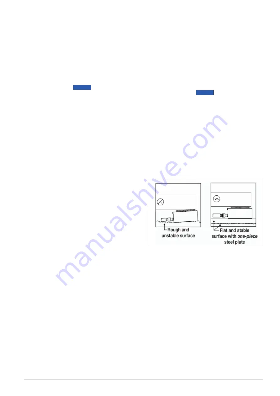
4.5 Cylinder Base Support
Be certain to provide adequate support for the cylinder
base. All CULP Series cylinders require a flat and stable
lifting surface that is capable of supporting the load
without settling. A one-piece steel plate of appropriate
size should be placed between the cylinder base and
the ground or other lifting surface.
Figure 3: Cylinder Base Support
Use of CULP Series cylinders on surfaces such as sand,
mud or dirt may result in loss of load and/or damage to
cylinder.
Always use a one-piece steel plate under a CULP Series
cylinder. To ensure proper support, be sure that the
plate extends under the entire surface of the cylinder
base. The cylinder base may become deformed and
permanently damaged if these instructions are not
followed.
4.6 Avoiding Side Load
Plan ahead to eliminate the presence of side load
forces (offset loading) when using hydraulic cylinders.
Side load can occur as a result of one or more of the
following conditions:
• An eccentric load on the plunger.
• A horizontal load on a structure.
• A shifting center of gravity.
• Structure and/or cylinder misalignment.
Содержание CULP10
Страница 2: ......
Страница 16: ...2022 Enerpac Tool Group All Rights Reserved www enerpac com...


