background image

Page 10

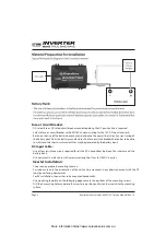
Inverter DC Input Connection:

 CAUTION

•  Reversing the DC Input terminal will damage the unit and cannot be repaired. Damage caused by reverse 

polarity connection is not covered by the warranty.

Hardwired Direct Connection:

• 

• 

Attach a positive (+) DC terminal (red) cable on the power inverter.

• 

Attach a negative (-) DC terminal (black) cable on the power inverter.

• 

Tighten the nut on each DC terminal.

• 

Connect the other end of the positive DC input cable to one of the terminals of the fuse holder or 
circuit breaker switch.

• 

Connect a DC positive input cable between the other terminals of the fuse holder or circuit breaker 
switch to the battery positive terminal.

• 

Connect the DC negative cable from the inverter to the negative post of the battery.

• 

Install the selected fuse to the fuse holder or switch on the circuit breaker.

• 

Unit is ready for use.

12v Lighter Plug Connection:

• 

Attach the red ring-type connector to the positive (+) DC terminal (red) on the power inverter.

• 

Attach the black ring type connector to the negative (-) DC terminal (black) on the Power inverter.

• 

Tighten the nut on each DC terminal.


Insert the light plug of this cable to the fused 12V lighter plug socket.


Make sure your load is not greater than the 120W while using the 12V lighter plug.

Connect unit with optional accessories using the Battery clips cable:

• 

Attach the red ring-type connector to the positive (+) DC terminal (red) on the power inverter.

• 

Attach the black ring type connector to the negative (-) DC terminal (black) on the Power inverter.

• 

Attach the negative (black) clip to the negative (-) battery terminal.

• 

Attach the positive (red) clip to the load side of the fuse or circuit breaker of the 12V battery bank 
as indicated on “Typical Wiring block diagram of the Power Inverter” on page 5.

• 

Unit is ready for use.

CAUTION: Please be sure all the connections are tight before the use of the unit.

Enerdrive Inverter Gen2 400W 12V Owners Manual Rev: 1.4

More information https://www.caravansplus.com.au

Содержание Gen2 TRUE SINE WAVE

Страница 1: ...Rev 1 4 More information https www caravansplus com au ...

Страница 2: ...num Plaza Queensland Australia4178 Enerdrivereservestherighttorevisethisdocumentandtoperiodicallymakechangestothecontenthereof without obligation or organization of such revisions or changes unless required to do so by prior arrangement Exclusions For Documentation And Product Usage technical or other information provided in its manuals or other documentation Assumes no responsibility or liability...

Страница 3: ...r DC Input Connection 10 5 Testing the Power Inverter 11 6 Unit Operation 11 Turn ON and OFF the unit 11 Understanding the Status indicator the unit warning fault alarm 11 Understanding the fan operation 12 AC Load on Power Inverter 12 Remote Switch optional Connection 12 Use of the Ignition Start Function on unit 12 Estimate Run time on Load 13 7 Troubleshooting 13 14 9 Warranty 15 5 Year Warrant...

Страница 4: ...er and all appropriate sections of this guide The Enerdrive Gen2 Inverter contains no user serviceable parts See Warranty section for how to handle product issues WARNING FIRE AND OR CHEMICAL BURN HAZARD WARNING SHOCK HAZARD KEEP AWAY FROM CHILDREN Avoid moisture ingress Never expose the unit to snow water etc Unit provides 230 VAC treat the AC output socket the same as regular wall AC sockets at ...

Страница 5: ...attention Keep unit away from moist or damp areas Avoid dropping any metal tool or object on the battery Doing so could create a spark or short circuit which goes through the battery or another electrical tool that may create an explosion LIMITATIONS OF USE Do not use in connection with life support systems or other medical equipment or devices Inverter is not to be used by persons with reduced ph...

Страница 6: ...Enerdrive Inverter Gen2 400W 12V Owners Manual Rev 1 4 More information https www caravansplus com au ...

Страница 7: ...More information https www caravansplus com au ...
Страница 8: ...resistance wire is required for all the DC connections between the inverter and the battery bank Use minimum 16mm2 cable with a maximum length of 1 5m for 12VDC inverter Inverter Installation Choose an appropriate mounting location For indoor use only the orientation of the unit can be mounted in any direction except with the DC Input panel facing downwards For RV installation the unit has to be m...

Страница 9: ...More information https www caravansplus com au ...
Страница 10: ...ach the red ring type connector to the positive DC terminal red on the power inverter Attach the black ring type connector to the negative DC terminal black on the Power inverter Tighten the nut on each DC terminal Insert the light plug of this cable to the fused 12V lighter plug socket Make sure your load is not greater than the 120W while using the 12V lighter plug Connect unit with optional acc...

Страница 11: ...output socket Understanding the Status indicator the unit warning fault alarm Status indicator Illuminated in green indicates unit is ON AC is available at the AC Output Socket Illuminated in green and alarm is beeping once every 2 second indicates a warning signal from the unit The unit is close to shutdown with one or more of the following warning conditions Over Temperature Warning Unit interna...

Страница 12: ...nses the internal temperature of the unit reach its preset level AC Load on Power Inverter Although the Power Inverter can provide high surge power some appliances may still trigger on the inverter protection system A higher power inverter is required for those appliances Remote Switch optional Connection The unit comes with a Remote port and an optional Remote Switch accessory EN1104 REM can be u...

Страница 13: ... output and Status light is OFF Turn unit ON No power to inverter Check fuse circuit breaker is either blown or turned OFF Status indicator is in green alarm beeps every 2 seconds Unit has detected a warning and is going to shutdown Verify the warning condition and make adjustment See Understanding the Status indicator and the unit warning and fault alarm in this manual Status indicator is in red ...

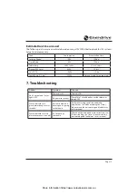
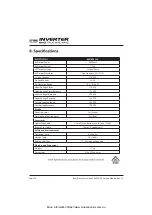
Страница 14: ...very 12 0 VDC Over Voltage Shutdown 15 9 VDC Over Voltage Recovery 15 0 VDC Display Power Indicator Yes Green Warning and Fault Indicator Yes Red Accessories Lighter Plug Cable 2 5mm2 2 conductors use for load 120W Battery Clips Cable 10mm2 2 conductors Safety and Environmental Operating Temp 0ºc to 40ºc Storage Temp 20ºc to 60ºc Relative Humidity 5 90 non condensing Weights and Dimensions Weights...

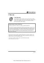
Страница 15: ... years from the date of purchase For full terms conditions and claim process refer to the Enerdrive website https enerdrive com au warranty If you have purchased your product in Australia you should be aware that This warranty is provided in addition to other rights and remedies held by a consumer at law Our goods come with guarantees that cannot be excluded under the Australian Consumer Law You a...

Страница 16: ...ERDRIVE PTY LTD P O Box 9159 Wynnum Plaza Queensland Australia 4178 Ph 1300 851 535 Fax 07 3390 6911 Email support enerdrive com au Web www enerdrive com au More information https www caravansplus com au ...
Отзывы: