6
3. Insert each cable through the cable hole, connect BNC cable and communication lines.
4. Unlock (4x) torx screws on the dome cover and fix the dome case firmly with supplied
mounting screws (4x), plastic anchors (4x), O-Rings (4x).
5. Adjust desired focus and scene by turning and moving the hemisphere by hand.
6. Replace the housing cover and secure with the torx screws (4x).
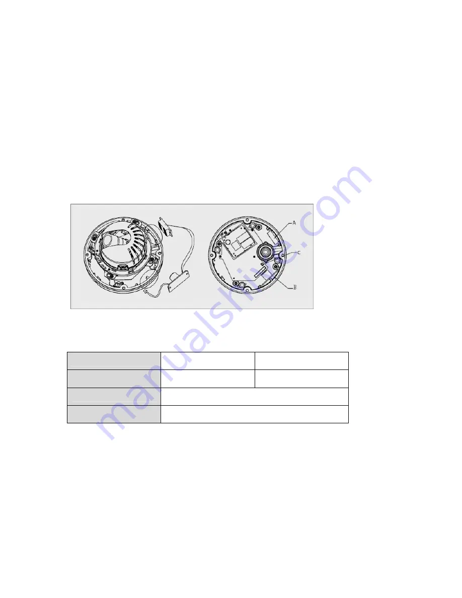
Heater Kit Installation (Optional)
1.
Place the heater element is slot “A”. Please ensure that the cables are facing upwards and
the heater is pointing towards the Dome.
2. Place the PCB in slot “B”. Please ensure that the PCB is facing inward with the connection
blocks at the top.
3. Place the plug in the Socket “C” (J3) which is found on the controller board.
[Heater Kit Installation]
NOTE
- Heater power consumption
Power Supply
AC24V
DC12V
Power Consumption
20Watt
10Watt
Heater On
at 41°F (5°C)
Heater Off
at 59°F (15°C)
[Heater Power Consumption]
-
Power
Use Certified/Listed Class 2 power source only.
Connection to an IP network
IP Assignment
See Page 7.


