background image

Levelflex FMP53 HART

Electrical connection

Hauser

23

7

Analog display device ; observe maximum load

8

Analog display device ; observe maximum load

9

Supply voltage for current output 2 (e.g. RN221N); Obeserve terminal voltage

10 Overvoltage protection module
11 Current output 2: Terminals 3 and 4
12 Terminal for the potential equalization line
13 Cable entry for current output 1
14 Cable entry for current output 2

This version is also suited for single-channel operation. In this case, current output 1

(terminals 1 and 2) must be used.

Содержание HART Levelflex FMP53

Страница 1: ...they are not a substitute for the Operating Instructions pertaining to the device Detailed information about the device can be found in the Operating Instructions and the other documentation Availabl...

Страница 2: ...Levelflex FMP53 HART 2 Endress Hauser Order code Ext ord cd Ser no www endress com deviceviewer Endress Hauser Operations App XXXXXXXXXXXX XXXXX XXXXXX XXX XXXX XX Serial number 1 3 2 A0023555...

Страница 3: ...uct identification 9 5 Storage Transport 11 5 1 Storage conditions 11 5 2 Transport product to the measuring point 11 6 Mounting 12 6 1 Mounting requirements 12 6 2 Mounting the device 13 6 3 Post ins...

Страница 4: ...on procedures and other facts which do not result in personal injury 1 1 2 Electrical symbols Symbol Meaning Symbol Meaning Direct current Alternating current Direct current and alternating current Gr...

Страница 5: ...A Reference to page Reference to graphic 1 2 3 Series of steps Result of a step Visual inspection 1 1 5 Symbols in graphics Symbol Meaning 1 2 3 Item numbers 1 2 3 Series of steps A B C Views A A B B...

Страница 6: ...wing measurements only Measured process variables level Calculated process variables Volume or mass in arbitrarily shaped vessels calculated from the level by the linearization functionality To ensure...

Страница 7: ...perational safety and reliability Carry out repairs on the device only if they are expressly permitted Observe federal national regulations pertaining to repair of an electrical device Use original sp...

Страница 8: ...of the device by affixing to it the CE mark 2 5 2 EAC conformity The measuring system meets the legal requirements of the applicable EAC guidelines These are listed in the corresponding EAC Declarati...

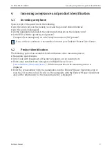
Страница 9: ...XA present If one of these conditions is not satisfied contact your Endress Hauser Sales Center 4 2 Product identification The following options are available for identification of the measuring devi...

Страница 10: ...er code Ext ord cd 4 2 D matrix code QR code For detailed information about interpreting the nameplate specifications refer to the Operating Instructions for the device Only 33 digits of the extended...

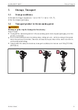
Страница 11: ...damaged or break away Risk of injury Transport the measuring device to the measuring point in its original packaging or at the process connection Do not fasten lifting devices hoisting slings lifting...

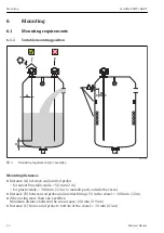
Страница 12: ...stances Distance A between wall and rod probe for smooth metallic walls 50 mm 2 in for plastic walls 300 mm 12 in to metallic parts outside the vessel Distance B between rod probe and internal fitting...

Страница 13: ...nics housing The connection cable is fixed to the probe on delivery The probe with connection cable and the electronics are adjusted to match each other They are marked by a common serial number Only...

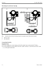
Страница 14: ...2 60 1 65 2 36 A0014793 4 Mounting the electronics housing using the mounting bracket dimensions mm In A Wall mounting B Pipe mounting Connecting the cable Required tools For the coupling nut at the h...

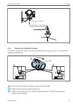
Страница 15: ...provide easier access to the connection compartment or display module the transmitter housing can be turned max 350 8 mm 8 mm 1 2 3 A0032242 1 Unscrew the securing screw using an open ended wrench 2...

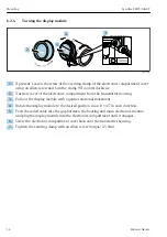
Страница 16: ...cs compartment from the transmitter housing 3 Pull out the display module with a gentle rotational movement 4 Rotate the display module to the desired position max 8 45 in each direction 5 Feed the co...

Страница 17: ...example Process temperature Process pressure refer to the chapter on Material load curves of the Technical Information document Ambient temperature range Measuring range m Are the measuring point iden...

Страница 18: ...open 1 2 4 20mA 1 channel overvoltage protection 16 A 7 B 4 20 mA 5 4 1 2 3 4 20 mA 5 4 1 2 3 6 A0011294 5 Terminal assignment 2 wire 4 20mA HART A Without integrated overvoltage protection B With in...

Страница 19: ...ion Endress Hauser 19 4 Analog display device Observe maximum load 5 Cable screen observe cable specification 6 4 20mA HART passive Terminals 1 and 2 7 Overvoltage protection module 8 Terminal for pot...

Страница 20: ...t 2 wire 4 20mA HART switch output A Without integrated overvoltage protection B With integrated overvoltage protection 1 Active barrier with power supply e g RN221N Observe terminal voltage 2 HART co...

Страница 21: ...Levelflex FMP53 HART Electrical connection Endress Hauser 21 9 Cable entry for 4 20mA HART line 10 Cable entry for switch output line 11 Overvoltage protection module...

Страница 22: ...4 4 4 4 4 20 mA 4 20 mA 10 B 4 20 mA 4 20 mA A0013923 7 Terminal assignment 2 wire 4 20 mA HART 4 20mA A Without integrated overvoltage protection B With integrated overvoltage protection 1 Connectio...

Страница 23: ...for current output 2 e g RN221N Obeserve terminal voltage 10 Overvoltage protection module 11 Current output 2 Terminals 3 and 4 12 Terminal for the potential equalization line 13 Cable entry for cur...

Страница 24: ...bserve maximum load 3 Connection for Commubox FXA195 or FieldXpert SFX350 SFX370 via VIATOR Bluetooth modem 4 Analog display device Observe maximum load 5 Signal cable including screening if required...

Страница 25: ...serve maximum load 3 Connection for Commubox FXA195 or FieldXpert SFX350 SFX370 via VIATOR Bluetooth modem 4 Analog display device Observe maximum load 5 Signal cable including screening if required o...

Страница 26: ...ssary connect the potential matching line to the external ground terminal 11 In order to ensure electromagnetic compatibility EMC Do not only ground the device via the protective earth conductor of th...

Страница 27: ...bus plug connector M12 or 7 8 the signal line can be connected without opening the housing Pin assignment of the M12 plug connector 2 1 3 4 A0011175 Pin Meaning 1 Signal 2 not connected 3 Signal 4 Gro...

Страница 28: ...re option A 2 Feature 010 of the product structure 3 For ambient temperatures Ta 30 C 22 F a minimum voltage of 14 V is required for the sartup of the device at the MIN error current 3 6 mA For ambien...

Страница 29: ...ly unit Non Ex Ex nA Ex nA ia Ex ic Ex ic ia Ex d ia XP Ex ta DIP CSA GP 13 5 to 35 V 3 R V U0 10 13 5 24 5 20 30 0 500 35 A0034971 Ex ia IS Ex ia Ex d ia IS XP 13 5 to 30 V 3 1 Feature 020 of the pro...

Страница 30: ...U0 10 12 23 20 30 0 500 A0022583 1 Feature 020 of the product structure option C 2 Feature 010 of the product structure 3 For ambient temperatures Ta 30 C 22 F a minimum voltage of 16 V is required fo...

Страница 31: ...nd FOUNDATION Fieldbus devices Product structure Feature 610 Accessory mounted option NA Overvoltage protection Technical data Resistance per channel 2 0 5 max Threshold DC voltage 400 to 700 V Thresh...

Страница 32: ...mensions mm in 1 Loosen the screw of the securing clamp on the connection compartment cover and turn the securing clamp 90 counterclockwise 2 Unscrew the connection compartment cover 3 Push the cable...

Страница 33: ...on 10 If present turn the cover lock so that it is located over the edge of the cover and then tighten 7 2 1 Plug in spring force terminals In the case of devices without integrated overvoltage prote...

Страница 34: ...ck Do the cables comply with the requirements Do the cables have adequate strain relief Are all cable glands installed securely tightened and leak tight Does the supply voltage match the specification...

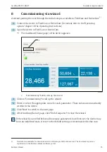
Страница 35: ...oning button calls up the wizard 3 Click on Commissioning to call up the wizard 4 Enter or select the appropriate value for each parameter These values are immediately written to the device 5 Click Ne...

Страница 36: ...ining tag and error symbol if an error is active 1 2 Measured value symbols 1 3 Measured value 1 4 Unit 2 Measured value display 1 bargraph 1 value 2 1 Bargraph for measured value 1 2 2 Measured value...

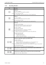
Страница 37: ...the key for 2 s for parameter If present opens the help text for the function of the parameter For text and numeric editor Pressing the key briefly Opens the selected group Carries out the selected ac...

Страница 38: ...Keylock on Opening and closing the context menu The user is in the operational display 1 Press for 2 s The context menu opens XXXXXXXXXX kg h 50 Setup Conf backup disp Env curve Keylock on A0033110 E...

Страница 39: ...l measuring conditions to process the measured value scaling linearization to configure the signal output Diagnostics Contains the most important parameters needed to detect and analyze operational er...

Страница 40: ...tions of the device BA01002F FMP53 HART 9 4 Setting the operating language Factory setting English or ordered local language XXXX XXX X X 20 50 Operation Setup Main menu 0104 1 Display language Englis...

Страница 41: ...evel F Full calibration span 1 Setup Device tag Enter tag for measuring point 2 Setup Distance unit Select distance unit 3 Setup Tank type Select tank type 4 Setup Tube diameter only if Tank type Bypa...

Страница 42: ...ys the signal quality of the level echo 11 Setup Mapping Confirm distance Compare the displayed distance to the real distance in order to start the recording of the mapping curve 9 6 User specific app...

Страница 43: ......

Страница 44: ...www addresses endress com 71385712 71385712...

Отзывы: