Oxymax W COS61
Wiring
Hauser
15
4.2
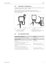
Connection via junction box
To extend the sensor connection beyond the length of the fixed cable, the connection has to take
place using a junction box VS (
15,
Always connect the sensor cable to the junction box with the SXP connector.
The extension to the transmitter depends on the transmitter version, i.e. field device or
panel-mounted instrument.
4.3
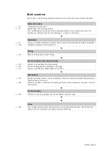
Post-connection check
a0004129-en
Fig. 15:
Junction box VS to the field device
1
SXP connector to the field device
2
SXP connector from the sensor
a0004130
Fig. 16:
Junction box VS to the panel-mounted
instrument
2
SXP connector from the sensor
3
Special measuring cable to the transmitter (OMK)
4
Transmitter connection compartment
Instrument status and specifications
Remarks
Are the sensor, assembly, junction box or cable damaged?
Visual inspection
Electrical connection
Remarks
Does the supply voltage of the transmitter match the specifications on the
nameplate?
110/230 V AC
24 V AC/DC
Are the installed cables strain-relieved and not twisted ?
Is the cable type route completely isolated?
Power cable/weak current cable
Are the power supply and signal cable correctly connected to the
transmitter?
Use the connection diagram of COM 2x3.
Are all the screws terminals properly tightened?
Are all the cable entries installed, tightened and sealed?
For cable entries lateral: cable loops
downwards for water to be able to drip off.
Are all the cable entries installed downwards or lateral?
1
2
82 / 3.23
80
/
3.15
mm / inch
3
2
YE
GY
PK
BU
BN
GN
WH
87
0
96
97
88
19
18
4


