BA 209F/00/en/04.04Nr. 52006313
Valid as of software version:V 01.02.00 (amplifier)V 01.02.00 (communication)
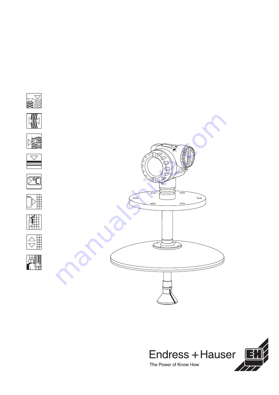
micropilot S
FMR 533Level-Radar
Operating Instructions
Страница 1: ...BA 209F 00 en 04 04 Nr 52006313 Valid as of software version V 01 02 00 amplifier V 01 02 00 communication micropilot S FMR 533 Level Radar Operating Instructions...
Страница 2: ...or input E see sketch input F see sketch only for bypass stilling well ok too small too big unknown manual displayed see sketch D and L are confirm or specify range suggestion 000 measured value Group...
Страница 3: ...peration 34 5 1 Quick operation guide 34 5 2 Display and operating elements 36 5 3 Local operation 39 5 4 Display and acknowledging error messages 42 5 5 HART communication 43 6 Commissioning 46 6 1 F...
Страница 4: ...ng to the instructions in this manual personnel must be authorised and suitably qualified The manual must have been read and understood and the instructions followed Modifications and repairs to the d...
Страница 5: ...e present Pay special attention to the gasket grooves and crevices where fluid may be present This is especially important if the fluid is dangerous to health e g corrosive poisonous carcinogenic radi...
Страница 6: ...in an explosion hazardous area Explosion hazardous area Symbol used in drawings to indicate explosion hazardous areas Devices located in and wiring entering areas with the designation explosion hazard...
Страница 7: ...tration No ATEX Safety information max measuring range in tank Degree of protection measuring range max permissible temperature on the antenna L00 FMR53xxx 18 00 00 en 003 ENDRESS HAUSER MICROPILOT S...
Страница 8: ...N250 PN16 C EN 1092 1 B11 316L 25 6 kg KDJ 10 K 200A RF JIS B2210 SS316L 13 8 kg KV2 10 K 150A RF JIS B2210 SS316L 9 9 kg K5J 10 K 250A RF JIS B2210 SS316L 22 9 kg XXJ with flange hub 316L XVU E H UNI...
Страница 9: ...the factory in a condition in which it is safe to operate The instrument complies with the applicable standards and regulations in accordance with EN 61010 Protection Measures for Electrical Equipmen...
Страница 10: ...using Turn housing Observe orientation when installing Installation in tank free space Mark on process connector facing the nearest tank wall The housing can be turned in order to simplify access to t...
Страница 11: ...upply matches your order 3 2 2 Transport Caution Follow the safety instructions and transport conditions for instruments of more than 18 kg Do not lift the measuring instrument by its housing in order...
Страница 12: ...4 Dimensions Micropilot S FMR 533 162 6 38 212 8 35 64 2 52 252 9 92 165 6 5 68 2 68 94 3 7 454 17 87 81 3 19 627 24 69 118 4 65 99 5 3 92 ENDRESS HAUSER Micropilot II 65 2 56 129 5 08 85 3 35 DIN AN...
Страница 13: ...emperature sensors etc inside the signal beam refer to beam angle It is essential that HiHi alarm is below the blocking distance BD and teh safety distance SD see page 15 Symmetrical installations 2 e...
Страница 14: ...beam and can be reflected off interfering installations Beamwidth diameter W as function of antenna type beam angle and measuring distance D Antenna size FMR 533 parabolic Beam angle 7 Measuring dista...
Страница 15: ...0 by default and generating an alarm in case the level rises inside the safety distance For Micropilot S FMR 533 with parabolic antenna this safety distance should be set to 0 5 m 20 The response of t...
Страница 16: ...3 as a medium of group A e g always use a stilling well Measuring range depending on product class for Micropilot S FMR 533 Note Inside the blocking distance a reliable measurement can not be guarante...
Страница 17: ...g distance The blocking distance BD is the minimum distance form the reference point of the measurement mounting flange to the medium surface at maximum level Blocking distance BD Free space Storage t...
Страница 18: ...ng the housing can be turned 350 in order to simplify access to the display and the terminal compartment The parabolic mirror must extend below the nozzle Align parabolic antenna vertically Mounting i...
Страница 19: ...can dismantle the parabolic reflector 4 bolts standard installation hinged flange manway hinge nozzle inclination rings with O ring Viton see construction hits on page 30 L00 FMR533xx 17 00 00 en 003...
Страница 20: ...rder to simplify access to the display and the terminal compartment Proceed as follows to turn the housing to the required position Undo the fixing screws 1 Turn the housing 2 in the required directio...
Страница 21: ...en reduced The bolt holes have been enlarged for adaption of dimensions therefore the flange needs to be properly aligned to the counterflange before the bolts are tightened Version Compatible with D...
Страница 22: ...3 Mounting Micropilot S FMR 533 22 Endress Hauser Preparation for the installation of the E H UNI flange L00 FMR532xx 00 00 06 en 002...
Страница 23: ...Micropilot S FMR 533 3 Mounting Endress Hauser 23 L00 FMR533xx 00 00 06 en 003...
Страница 24: ...ot recommended for highly accurate measurements due to the unsteady movements of the floating roofs A special reflector can be used for applications on floating roofs not for FMR 532 with planar anten...
Страница 25: ...ioning of the reflector on a floating roof The upper edges of the reflector have to be aligned horizontally For slanted locations e g dome shaped floating roof the feet must be extended accordingly Pl...
Страница 26: ...uch that the radar beam is directed straight to the product surface Note The inclination device shown below is presented as construction proposal only 3 0 5 H max 200 t 2 3 t components 2 inclination...
Страница 27: ...nment unit can be adjusted up to 15 by means of an inclination device The purpose is to align the antenna axis such that the radar beam is directed straight to the product surface Note The alignment u...
Страница 28: ...rument correspond to the measuring point specifications such as process temperature pressure ambient temperature measuring range etc Is the flange marking correctly aligned see Page 10 ff Have the fla...
Страница 29: ...ound screening of the line 5 on sensor side Make connection see pin assignment Tighten cable gland 4 Screw off housing cover 2 Switch on power supply Before connection please note the following The po...
Страница 30: ...ential When you use the measuring system in hazardous areas make sure you comply with national standards and the specifications in the safety instructions XA s Make sure you use the specified cable gl...
Страница 31: ...r consumption Max 330 mW at 16 V max 500 mW at 24 V max 600 mW at 30 V Current consumption Max 21 mA 50 mA inrush current Power supply For stand alone operation recommended via e g E H RN 221 N mm acc...
Страница 32: ...D E F Hot Key Hot Key M N O W X Y Z 4 7 2 5 8 0 375 FIELD COMMUNICATOR 3 6 9 9 6 DELTABAR ONLINE 1 QUICK SETUP 2 OPERATING MENU 4 SV 0 C 3 PV 352 mbar HELP SAVE dsdmdm df das asdas fa asas la power su...
Страница 33: ...e reliable potential matching Installation with additional overvoltage protector HAW 262 Z see XA 081F A Safety instructions for electrical apparatus certified for use in explosion hazardous areas Con...
Страница 34: ...cted e g tank shape 002 with or b confirms selection appears in front of the selected parameter c confirms the edited value system quits Edit mode d interrupts selection system quits Edit mode a Press...
Страница 35: ...setup 00 function group include e g tank shape 002 medium property 003 process cond 004 empty calibr 005 etc If for example the application of the instrument is to be changed carry out the following...
Страница 36: ...1 Display Liquid crystal display LCD Four lines with 20 characters each Display contrast adjustable through key combination Fig 6 Display L00 FMR53xxx 07 00 00 en 003 ENDRESS HAUSER E 21dB 09C 10 00...
Страница 37: ...arning LOCK_SYMBOL This lock symbol appears when the instrument is locked i e if no input is possible COM_SYMBOL This communication symbol appears when a data transmission via e g HART PFOFIBUS PA or...
Страница 38: ...ed data storage The radar instruments Micropilot S continuously monitor the compliance with accuracy requirements for custody transfer measurements according to OIML R85 If the accuracy cannot be main...
Страница 39: ...oup The lock is shown on the display by the symbol and can be released again either via the display or by communication Hardware lock The instrument is locked by pressing the O and S and F keys at the...
Страница 40: ...pressing the O and S and F keys at the same time the user is asked to enter the unlock parameter 100 for HART devices Caution Changing certain parameters such as all sensor characteristics for example...
Страница 41: ...ted in the linearisation 04 function group List of functions that are affected by a reset 555 History Reset After mounting and aligning the equipment carry out a history reset before switching on the...
Страница 42: ...ng error message is displayed Indicated by a flashing symbol For a description of the codes see Table 9 2 on Page 76 E Alarm Warning Configurable e g loss of echo level within the safety distance Indi...
Страница 43: ...t commissioning securing of data signal analysis and documentation of the instruments It is compatible with the following operating systems Win95 Win98 WinNT4 0 Win2000 and Windows XP The ToF Tool sup...
Страница 44: ...n Micropilot S FMR 533 44 Endress Hauser Menu guided commissioning Signal analysis via envelope curve Connection options Service interface with adapter FXA 193 see Page 32 HART with Commubox FXA 191 s...
Страница 45: ...given in the following E H documentation System Information SI 018F 00 en Commuwin II Operating Manual BA 124F 00 en Commuwin II operating program Connection The table provides an overview of the Com...
Страница 46: ...device When the instrument is switched on for the first time the following messages appear on the display After 5 s the following message appears After 5 s or after you have pressed Fthe following mes...
Страница 47: ...n 0A6 F full calibr span level display SD safety settings BD blocking dist settings in 015 settings in 059 for bypass stilling well description see BA 217F measuring cond measuring cond pipe diameter...
Страница 48: ...nly be entered if stilling well was selected beforehand in the tank shape 002 function Certain functions e g starting an interference echo mapping 053 prompt you to confirm your data entries Press O o...
Страница 49: ...e selected in the no of decimals 095 function The length of the bargraph corresponds to the percental value of the present measured value with regard to the span 6 4 1 Function group basic setup 00 Fu...
Страница 50: ...4 10 10 2 Treat Ammonia NH3 as a medium of group A i e always use a stilling well Product class DK r Examples A 1 4 1 9 non conducting liquids e g liquefied gas 2 B 1 9 4 non conducting liquids e g b...
Страница 51: ...d if you select the measuring conditions standard or calm surface We strongly recommend that in the case of rough product surfaces or rapid filling you activate the appropriate application parameters...
Страница 52: ...r than the point at which the radar beam hits the bottom of the tank Function full calibr 006 This function is used to enter the distance from the minimum level to the maximum level span In principle...
Страница 53: ...y the Micropilot It is only necessary to enter the pipe diameter for applications in a bypass or stilling well Function dist meas value 008 The distance measured from the reference point to the produc...
Страница 54: ...ven in this case dist too small At the moment an interference is being evaluated Therefore a mapping is carried out including the presently measured echoes The range to be suppressed is suggested in t...
Страница 55: ...point is always the reference point of the measurement see Page 47 ff This value can be edited by the operator For manual mapping the default value is 0 m Function start mapping 053 This function is u...
Страница 56: ...ust be carried out check distance 051 Distance correct level incorrect check empty calibr 005 Function history reset 009 By this function a history reset of the device is performed i e the corresponda...
Страница 57: ...y discover and correct measuring errors due to this multiple path propagation This is because it uses two independent sets of information when evaluating reflection signals Firstly it evaluates the am...
Страница 58: ...more than 0 1mm to the value entered in the function group basic setup 00 The errors which occur as a result are linear and can be corrected with a dip table containing at least two entries The Microp...
Страница 59: ...nstrument is lead sealed and accurate to the nearest mm is active and is held active neg Custody mode instrument is lead sealed and accurate to the nearest mm is activated and not held e g because the...
Страница 60: ...ncorrected measurement values it is recommended to use the semi automatic mode of the dip table to enter new data pairs In this case the first dip value should be entered immediately after the basic c...
Страница 61: ...the ToF Tool Note Make your inputs into the dip table in semi automatic mode We advise you to leave auto correction 031 activated on while you enter your inputs Caution After entering one or more poin...
Страница 62: ...ip table can be read You can enter the dip value only When there are new value pairs the current level or distance is accepted as the measured value table on The dip table is switched on table off The...
Страница 63: ...ase the number of free table entries stands at minimum value 0 edit point The displayed value pair can be changed Only the dip value can be changed with semi automatic input mode Caution To accept the...
Страница 64: ...f the table is empty you can still select this option However the displayed value does not change previous point This scrolls up in the table If the table is empty you can still select this option How...
Страница 65: ...unction recording curve 09B This function determines whether the envelope curve is read as single curve or cyclic Note If the envelope curve mode is active on the display the measured values are updat...
Страница 66: ...Tool operating program and establish a connection Select the basic setup function group in the navigation bar The following display appears on the screen Basic Setup step 1 5 Status image Enter the me...
Страница 67: ...r a description see Page 49 medium property for a description see Page 50 process cond for a description see Page 51 Basic Setup step 3 5 If dome ceiling is selected in the tank shape function the fol...
Страница 68: ...description see Page 52 full calibr for a description see Page 52 If stilling well or bypass is selected in the tank shape function the following display appears on the screen empty calibr for a desc...
Страница 69: ...52 full calibr for a description see Page 52 Basic Setup step 4 5 This step starts the tank mapping The measured distance and the current measured value are always displayed in the header A descripti...
Страница 70: ...very weak or there is a heavy interference echo an orientation of the Micropilot can help optimise the measurement increase of the useful echo reduction of the interference echo see Quick installation...
Страница 71: ...ating program and establish a connection Select the mounting calibr function group in the navigation bar The following display appears on the screen Mounting calibration step 1 2 auto correction descr...
Страница 72: ...Hauser Mounting calibration step 2 2 dip table mode description see Page 61 meas v description see Page 62 dip value see Page 62 dip table handl description see Page 63 dip table state description see...
Страница 73: ...mplete Micropilot or electronic module has been replaced the parameters can be downloaded into the instrument again via the communication interface Prerequisite to this is that the data were uploaded...
Страница 74: ...ainless steel is available for outdoor mounting order code 543199 0001 The shipment includes the protective cover and tension clamp Commubox FXA 191 HART For intrinsically safe communication with ToF...
Страница 75: ...Micropilot S FMR 533 9 Trouble shooting Endress Hauser 75 9 Trouble shooting 9 1 Trouble shooting instructions L00 FMR53xxx 19 00 00 en 010...
Страница 76: ...nics defect E2PROM defective reset if alarm prevails after reset exchange electronics A115 electronics defect general hardware problem reset if alarm prevails after reset exchange electronics A116 dow...
Страница 77: ...mapping active wait some seconds until alarm disappears W601 linearisation ch1 curve not monotone linearization not monotonously increasing correct linearisation table W611 less than 2 linearisation...
Страница 78: ...eck table no Measurement in bypass or stilling well yes 1 Is bypass or stilling well selected in tank shape 002 2 Is the pipe diameter 007 correct no Is an FAR 10 antenna extension being used yes 1 of...
Страница 79: ...he range of the blocking dist 059 there is no echo evaluation Adapt the value 3 If possible do not select central installation position 4 Perhaps use a stilling well E 641 loss of echo Level echo is t...
Страница 80: ...ses an increase in the strength of the measuring signal Proceed as follows Warning Subsequent alignment can lead to personal injury Before you unscrew or loosen the process connection make sure that t...
Страница 81: ...sel empty no interference echo d Vessel empty interference echo obtained 7 Fix the flange or threaded boss in this position If necessary replace the seal 8 Carry out tank mapping siehe Kapitel 6 1 bzw...
Страница 82: ...erial number which is printed on the measuring transducer nameplate see Page 7 ff The corresponding spare part number also appears on each spare part Installation instructions are given on the instruc...
Страница 83: ...Micropilot S FMR 533 9 Trouble shooting Endress Hauser 83 L00 FMR533xx 00 00 06 en 002...
Страница 84: ...imply exchanging parts When repairing certified instruments the relevant regualtions must be followed For FM approved instruments it is forbidden to make any changes to the instrument that are not exp...
Страница 85: ...do not hesitate to contact your E H representative Software version Date Software changes Documentation changes V 1 00 00 12 2000 Original software Operated via ToF Tool Commuwin II from version 2 05...
Страница 86: ...The Micropilot S FMR 530 with horn antenna can be used as an alternative for small nozzle diameters The instruments are equipped with a passive 4 20 mA output with HART protocol Input Measured variab...
Страница 87: ...nd relative error at 10 equidistant points during the final test A Laser Interferometer Jenaer Messtechnik ZLM 500 with an absolute accuracy of 0 1 mm is used as a reference for the free space measure...
Страница 88: ...he LC display is reduced A weather protection cover should be used for outdoor operation if the instrument is exposed to direct sunlight Storage temperature 40 C 80 C 40 F 176 F Climate class DIN EN 6...
Страница 89: ...n class of housing IP code EN 61010 Safety regulations for electrical devices for measurement control regulation and laboratory use EN 61326 Emissions equipment class B compatibility appendix A indust...
Страница 90: ...ustomer unit check distance distance ok dist too small manual dist unknown dist too big low output limit off on back to home enter time default 100 s clear last error protocol sw no ramp min empty cal...
Страница 91: ...o small dist too big manual dist unknown auto correction off on offset plot settings will be added to the measured level envelope curve env curve FAC env curve cust map output current ackn alarm overs...
Страница 92: ...handl dip table state 04 linearisation V3 level ullage linearisation customer unit table no input level input volume max scale diameter vessel 05 extended calibr V4 check distance range of mapping st...
Страница 93: ...x Endress Hauser 93 11 3 Description of functions Note A detailed description of the function groups functions and parameters is given in the documentation BA 217F 00 en a description of the instrumen...
Страница 94: ...n of the radar impulse at the product surface The unambiguous signal identification is accomplished by the PulseMaster software based on many years of experience with time of flight technology The mm...
Страница 95: ...mm However for these diameters no custody transfer approval is available The Micropilot S FMR 533 with parabolic antenna is preferred for free space measurements The Micropilot S FMR 530 with horn an...
Страница 96: ...375 with a Personal Computer Commubox FXA 191 and the operating software COMMUWIN II respectively ToF Tool With a Personal Computer TSM Tank Side Monitor and the operating software FuelsManager System...
Страница 97: ...at 2mm for radar measuring devices in Germany Essentially this proves that the devices are weight and measure approved The devices must not however be used in custody transfer mode straight away The...
Страница 98: ...by the key symbol Micropilot S radar devices continuously monitor the compliance with accuracy requirements for custody transfer measurements according to OIML R85 If for example the accuracy cannot b...
Страница 99: ...onitor guarantee connectivity to nearly any of the existing industry standard tank gauging protocols Optional connectivity of analog 4 20 mA sensors digital I O and analog output simplify full tank se...
Страница 100: ...ast one of the following patents Further patents are pending US 5 387 918 i EP 0 535 196 US 5 689 265 i EP 0 626 063 US 5 659 321 US 5 614 911 i EP 0 670 048 US 5 594 449 i EP 0 676 037 US 6 047 598 U...
Страница 101: ...calibration 47 52 67 69 Engineering hints 13 Envelope curve 65 Error messages 42 F Foam 15 Foam surface 15 Free space 16 Full calibration 47 52 67 69 Function groups 35 Functions 35 G Green LED 37 Gr...
Страница 102: ...pprovals 89 Roof reflector 24 S Safety conventions 6 Scope of delivery 9 Sealing 36 Select the language 46 Selection menu 34 Service adapter FXA 193 74 Smallest possible measuring range 15 Software hi...
Страница 103: ...o poisonous o harmful of health o biological hazardous o inflammable o safe Please mark the appropriate warning hints 5HDVRQ IRU UHWXUQ BBBBBBBBBBBBBBBBBBBBBBBBBBBBBBBBBBBBBBBBBBBBBBBBBBBBBBBBBBBBBBBB...
Страница 104: ...mbia Bogota D C Colsein Ltda Tel 01 2 36 76 59 Fax 01 6 10 78 68 Costa Rica San Jose Euro Tec S A Tel 2 20 28 08 Fax 2 96 15 42 Ecuador Quito Insetec Cia Ltda Tel 02 2 26 91 48 Fax 02 2 46 18 33 El Sa...