


IM7310A Rev A
5
April 7
th
, 2020
5.1.
Mounting Surface
The mounting surface should be clean and free of burrs. Two #0-80 tapped holes, 0.2 inch minimum depth should be
spaced 0.3 inches (7.62 mm) apart. A 32 micro inch rms surface finish with flatness of 0.0001 inches is
recommended for the area that will contact the angular rate sensor. The rotational axis of the unit is perpendicular
to the mounting surface, so the angular alignment of the two mounting holes is not critical. The location of the
mounting holes is not critical either, the angular rate sensor can be mounted at the center or close to the edge of the
mounting surface of the rotational substrate.
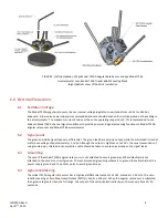
5.2.
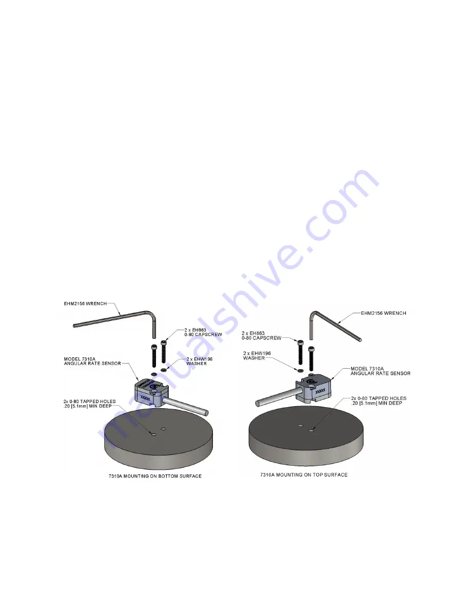
Screw Mount
To screw mount Model 7310A to mounting surface, use the supplied mounting washers (EHX196, 18-8 CRES),
mounting screws (EH863, 0-80 x 3/8’’, alloy steel, black oxide finish) and Allen wrench (EHM2156, alloy steel, black
oxide finish) as shown in Figure 1.
Remove the unit from the shipping container. Place the unit on the mounting surface and align the mounting holes.
Slide the washers over the screws. Using the supplied wrench or a torque wrench, tighten the screws to 4 lbf-in (0.45
Nm). This is roughly equivalent to finger tight with the supplied wrench.
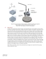
The Model 7310A angular rate sensor can be mounted on either the bottom surface of the sensor, as shown in Figure
1(a), or the top surface of the sensor, as shown in Figure 1(b). The rotation arrow mark printed on the top and
bottom surface of the angular rate sensor indicates the positive rotation direction. When mounted on bottom
surface, the angular rate sensor outputs a positive voltage in response to a clockwise rotation. When mounted on
top surface, the angular rate sensor outputs a positive voltage to an anti-clockwise rotation.
FIGURE 1 (Left) Screw Mount of Model 7310A Angular Rate Sensor (on sensor bottom)
(Right) Screw Mount of Model 7310A Angular Rate Sensor (on sensor top)