


ENDEVCO 2680
INSTRUCTION MANUAL
IM2680
Page 1-2
must be sealed to the case with solder, glyptol or epoxy for the Charge Amplifier to meet humidity
specifications during operation.
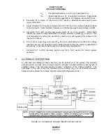
Charge Amplifiers shipped as single items of equipment have the Gain Potentiometer set to the
maximum rated gain of the Charge Amplifier, and the Gain-Access Screw temporarily seated in
the threaded access hole. Users of the Charge Amplifier are then required to adjust the gain to a
desired gain setting prior to application of a Charge Amplifier (see Paragraph 4.2). Table 1-2 lists
the gain ranges for each "M" series (M1 thru M7, M12 and M14) of Charge Amplifiers.
____________________________________________________________________________
___Power Requirements____
Current
Basic Input
Output
DC-to-DC Voltage M1-M7 M12, M14
Model Connector
Connector
Accessories
Conv.
VDC
mA DC mA DC _
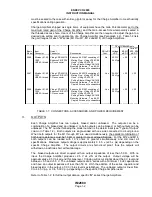
2680
Microdot 51-49 Viking VR5/4AG15
Endevco Kit 21997 consisting of:
No
20-32 V
< 20
< 25
10-32
Endevco P/N EP30 Mating Plug - Viking VP5/4CE6
28 V typ
UNF-2A thread 5-Pin connector
Hood - Viking VS4/16C5
Potting Sleeve-VikingVS4/16C9
Mounting Hardware - Two #6-32
Captive Screws w/ Lockwashers
2681
Microdot 51-49 Viking VR7/4AG15
Endevco Kit 23318 consisting of:
Yes
24-32 V
< 30
< 35
10-32
Endevco P/N EJ277 Mating Plug - Viking VP7/4CE6
28 V typ
UNF-2A thread 7-Pin connector
Hood - Viking VS4/16C5
Potting Sleeve-VikingVS4/16C9
Mounting Hardware - Two #6-32
Captive Screws w/ Lockwashers
2680
Microdot 51-49 Viking VR7/4AG15
Endevco Kit 21997 consisting of:
Yes
20-32 V
< 30
< 35
10-32
Endevco P/N EJ277 Mating Plug - Viking VP5/4CE6
28 V typ
UNF-2A thread 7-Pin connector
Hood - Viking VS4/16C5
Potting Sleeve-VikingVS4/16C9
Mounting Hardware - Two #6-32
Captive Screws w/ Lockwashers
______________________________________________________________________________________________________
TABLE 1-1: CONNECTORS, ACCESSORIES, AND POWER REQUIREMENT
3.
OUTPUTS
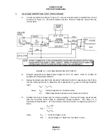
Each Charge Amplifier has two outputs, biased and/or unbiased. The outputs can be a
combination of a biased and an unbiased, or both outputs can be biased, or both outputs can be
unbiased. The "M" number following the model number is the determinant (see "Types of Output"
column in Table 1-2). Both outputs are single-ended with one side connected to circuit ground.
When both outputs for the M1 through M7 are used simultaneously, the parallel combination of
both load resistances must be 10 k
Ω
or greater to meet all specifications. For the M12 and M14,
both outputs can be loaded with 10 k ohms or greater simultaneously and still meet all
specifications. Maximum output voltage is approximately 0 to 5 v (±2.5 v pk) depending on the
specific Charge Amplifier. The output circuits are short-circuit proof, thus the outputs will
withstand an indefinite short without damage.
The biased outputs are direct coupled with an output impedance of less than 50 Ω. With no
input, the Charge Amplifier pr2.5 V dc
±
3% at the output. Output voltage will be
approximately ±2.5 V pk around this bias level. Clipping will occur slightly about the 0 V level and
b5.0 and +5.3 V. The unbiased outputs are in series with a minimum 16 uF capacitance
and have an output impedance o
f less than 50 Ω. With the addition of the series capacitor and
bleed resistor in the output, a 0.00 V bias level is established. The unbiased output is linear from
0 to 4.65 V p-p, or 0 to 5.00 V p-p, depending on the specific Charge Amplifier used.
Refer to Table 1-2 for further output data on specific "M" series Charge Amplifiers.


