


ENDEVCO 2680
INSTRUCTION MANUAL
IM2680
Page 3-2
3.
VOLTAGE INSERTION TEST PROCEDURE
A.
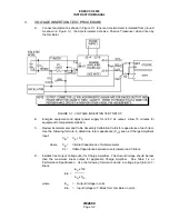
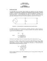
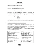
Connect equipment as shown in Figure 3-1. Ensure Accelerometer is isolated from ground.
As shown in Figure 3-1, the Accelerometer acts as a Passive Transducer when driven by
the Oscillator.
FIGURE 3-1: VOLTAGE INSERTION TEST SETUP
B.
Energize equipment and adjust power supply for +28 V dc output. Allow 15 minutes for
equipment to temperature stabilize.
C.
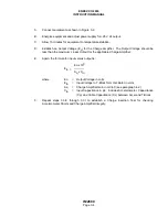
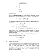
Review Accelerometer and Cable Assembly Calibration Cards for capacitance of each item.
Use the following formula to determine total capacitance (Cin) seen at Charge Amplifier's
input:
Cin = Cp + Cc
where
Cp = Internal Capacitance of Accelerometer
Cc = Cable Capacitance between Accelerometer and T-Block
D.
Establish an Output Voltage (Eo) for Charge Amplifier. The Output Voltage should be less
than the maximum linear output for applicable Charge Amplifier. See Table 1-2 or
Performance Specification. Use the following formula to obtain a voltage input (Ein) to T-
Block:
Eo x 103
Ein =
Aq x Cin
where
Eo = Output Voltage in volts
Ein = Input Voltage to T-Block form Oscillator in volts


