background image


EDM05-01v6 Time Distribution Server User Guide - Introduction 


©2011 Endace Technology Ltd.  Confidential - Version 6 - November 2011 

5


Rear Panel 

The TDS2 Server Module rear panel is shown below: 


Expansion 

If additional time synchronization outputs are required you can expand the capacity of the server module by adding 
TDS6 Expansion units. One TDS2 Server Module with the maximum  number of TDS6 Expansion Units provides 26 
time synchronization outputs (six on each TDS6 Unit and two on the TDS2 Module) all derived from a single external 
standardtime synchronization source. 

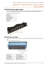
The TDS6 time synchronization outputs use RJ45 connectors and can be connected to the time synchronization 
sockets on the front bracket of a DAG card using standard Ethernet cables and patch equipment. 


Product Specifications 

TDS2/TDS6 


Power Supply:


12V DC, 2.5 A

Form Factor:


3 per 1U 19 inch rackmount

Dimensions:


Front panel Width: 

140.5 mm (5.5 in) 

Rear panel Width: 

95.0 mm (3.7 in) 

Height: 


31.9 mm (1.3 in) 

Length: 


107.6 mm (4.2 in) 

Operating Temperature:


10 °C~35 °C (50 °F~95 °F)

Humidity:


8%~90% non-condensing

Typical power consumption:

  1 W (1x TDS2)

Maximum power 

consumption:


6 W (1x TDS2, 4x TDS6, 1x Acutime 2000)


Acutime 2000 

See product documentation. 


Cabling Limitations 

To prevent interference and timing jitter, Endace recommends not exceeding the following lengths: 

TDS2/TDS6 to TDS6:


10 m (30 ft)

TDS2/ TDS6 to DAG card:


100 m (300 ft)

Endace TTL adapter to 

TDS2:


10 m (30 ft)

Acutime 2000 to TDS2:


See Acutime 2000 product documentation.


Содержание EDM05-01

Страница 1: ...Time Distribution Server User Guide EDM05 01...

Страница 2: ...ate the user s right to operate this equipment in a Class A industrial environment Disclaimer Whilst every effort has been made to ensure accuracy neither Endace Technology Limited nor any employee of...

Страница 3: ...Source 7 Connecting to a Time Reference Source 7 CDMA 7 GPS 7 TTL 8 Connecting to a DAG Card 8 Connecting to a Computer 9 Verifying Time Packets 9 Software Configuration 10 Using the TDS6 Expansion U...

Страница 4: ......

Страница 5: ...tances where it is not practical to run cable to an externally mounted GPS receiver time reference signals from a CDMA cellular network may be used instead CDMA base stations use a GPS receiver to col...

Страница 6: ...r connecting up to two DAG cards Chain out to enable connections of TDS6 modules to provide signal outputs for additional DAG cards from just one external time reference Status LED indicators Accepts...

Страница 7: ...nected to the time synchronization sockets on the front bracket of a DAG card using standard Ethernet cables and patch equipment Product Specifications TDS2 TDS6 Power Supply 12V DC 2 5 A Form Factor...

Страница 8: ...le Acutime 2000 GPS receiver can be purchased as part of the Acutime 2000 Synchronization Kit Trimble part number 40986 00 The kit includes integrated antenna receiver 100ft cable power supply and sig...

Страница 9: ...end to the 12VDC source Caution If you are connecting the TDS Module to an unprotected power source you should use an external 2A fuse Connecting to a Time Reference Source CDMA Follow the steps below...

Страница 10: ...e connect the TTL time source to the Endace TTL adapter below 3 Set the Signal Source switch on the front panel of the TDS2 Module to GPS 4 The PPS LED on the TDS2 Module will flash to indicate it is...

Страница 11: ...the signal is being generated by a CDMA receiver you can view the time packet on the computer using a standard terminal emulator The Trimble Acutime Gold outputs binary formatted data in the serial t...

Страница 12: ...29 0 Trimble Palisade GPS Stratum 1 Set packet delay fudge 127 127 29 0 time1 0 020 and set flag2 to turn off event polling fudge 127 127 29 0 flag2 1 3 Ensure the ntp software is set to start at boot...

Страница 13: ...nchronization outputs derived from a single TDS2 Module connection Each time synchronization output is independently driven The TDS6 Unit power the TDS2 module through the chain cables A TDS6 Expansio...

Страница 14: ...ashing check the TDS2 module is powered and all connections are correct Adding Additional TDS6 Expansion Units You can couple a number of TDS6 Expansion Units together like a daisy chain to extend tim...

Страница 15: ...5 SERIAL Out 6 PPS Out 7 NC 8 NC RS232 DB9 CDMA Input The TDS2 Server Module has one male DB9 input for connecting the Endrun Technologies Praecis Ct CDMA time receiver using standard Ethernet cables...

Страница 16: ...RS422 Chain Output A two port six position six contact modular jack provides direct connection for up to two TDS6 modules The pin out configuration is shown below 1 GND 7 GND 2 PPS Out 8 PPS Out 3 SE...

Страница 17: ...mber 2011 15 DB25 to DB9 GPS Adapter Plug A custom cable will be required when using a DAG card as a time source for a TDS 2 module RJ45 plug to DB9 male or 4 pin connector plug to DB9 male The pin ou...

Страница 18: ......

Страница 19: ...RJ45 modular jack provides time synchronization outputs to the time synchronization input on the DAG card front bracket The pin out configuration is shown below 1 N C 2 N C 3 PPS Out 4 SERIAL Out 5 SE...

Страница 20: ......

Страница 21: ...uary 2009 Minor changes Added TTL and DAG Master cable 4 August 2009 Minor changes Updated Connecting to a Computer 5 December 2009 Updated TDS6 RS422 pin out diagram Added Product specifications 6 No...

Страница 22: ......

Отзывы: