background image

I

NSTALLING

 T

HE

 860XC PRO E

THERNET

 E

XTENDER

 K

IT


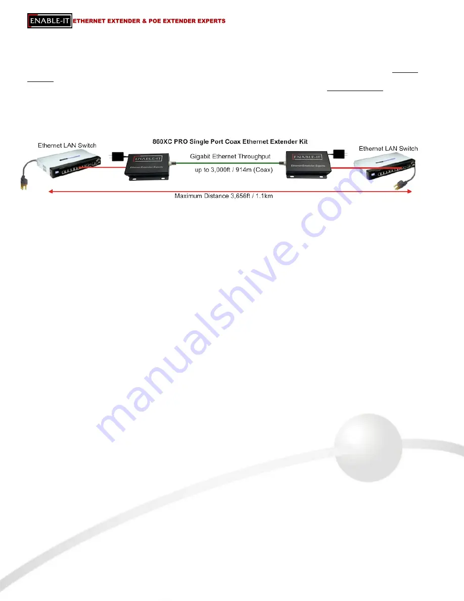
The Enable-IT 860XC PRO Gigabit Coax Ethernet Extender Solution has a distance reach of up to 3,000ft 

(915m) over 75 Ohm rated RG6 cabling between the 860XC PRO units. You can add an additional 328ft 

(100m) onto the end of each 860XC PRO LAN output ports for a total distance of 3,656ft (1.1km) from device 

extension to device extension.  

A site survey of the wiring and installation planning are highly recommended. For highest performance use 75 

Ohm rated RG6 cabling for the interlink wiring  


We highly recommend that you perform a quick out of the box test to ensure the working order of your 

Enable-IT 860XC PRO Gigabit Coax Ethernet Extender units prior to installing.  This will also serve to 

familiarize you with how easy the process should be. Follow the steps below to perform the Out Of the 

Box Test.


Step 1


- Attach the 12V DC power adapters to each 860XC PRO unit and power up the units. 

              Each of the respective Power LEDs will indicate the units are receiving power. 


Step 2

 - Connect the 860XC PRO units together using your own RJ6 75 Ohm Coax cable – attach 

              to the coax cable to the Interlink port on each 860XC PRO unit as shown by the green line connecting                       


  the units in the diagram above. On both units, the green Link LED will blink rapidly when it sees the  


  partner unit and connects successfully. The LAN Port LEDs will blink as they see passing traffic (data).


Step 3


- Attach and test to confirm your LAN Equipment works through the 860XC PRO extension, connect 

              your Ethernet LAN to the 860XC PRO Injector unit LAN port and the remote device/s to the 860XC       


  PRO Extender LAN port and test connectivity. Green Blink rapidly when it sees the partner unit –  


  indicates working connection – Green No LED indicates it cannot see the partner unit.


LAN/Power side LEDs 


Mode 


– Green LED    (LED On = CO unit, LED Off = CPE unit) 


         Link 


– Green Blink rapidly when it sees the partner unit – indicates working connection 


    – Green No LED indicates it cannot see the partner unit. 


Power


    – Green Solid LED indicates the unit is receiving 12V power.


LAN Sync. 

– Green LED 


           Off  

 =  No device attached or detected. 


           On  

 =  Solid, indicates the presence of local LAN. 


LAN Act.   

– Yellow LED 


          Blinking =  Indicates the presence of local LAN traffic.

The Green Link LEDs will blink rapidly when it sees the partner unit and connects successfully. 


This confirms basic proper operation of the units.


All Rights Reserved © 1997 - 2020  Enable-IT

, Inc.                                                                               Page   of 

2

6

Содержание 860XC PRO

Страница 1: ...Enable IT 860XC PRO Gigabit Coax Ethernet Extender Kit Quickstart Guide Professional Grade Networking All Rights Reserved 1997 2020 Enable IT Inc ...

Страница 2: ...oax cable to the Interlink port on each 860XC PRO unit as shown by the green line connecting the units in the diagram above On both units the green Link LED will blink rapidly when it sees the partner unit and connects successfully The LAN Port LEDs will blink as they see passing traffic data Step 3 Attach and test to confirm your LAN Equipment works through the 860XC PRO extension connect your Et...

Страница 3: ...s wire run The 860XC PRO BNC Interlink port carries this 1 pair signaling and power over the coax For all wiring you will need to crimp a 75 Ohm BNC Female head to each end of the contiguous wire run straight through We recommend using 75 Ohm coaxial cable as it is optimized for high throughput frequencies isolated from cross talk noise Insert the completed BNC ends into the 860XC PRO BNC Interlin...

Страница 4: ...b Site https support enableit com Returning Products for Warranty Repair Enable IT warrants to the original purchaser of the Product you or the End User that for the limited lifetime period commencing on the date the Product was purchased the Warranty Period the Product will be substantially free from defects in materials and workmanship under normal use and conditions This warranty does not apply...

Страница 5: ... If authorized by Enable IT to return a Product which does not conform to the warranty set forth above the End User must 1 obtain a return materials authorization RMA number from Enable IT by contacting the Customer Service Dept at 888 309 0910 between the hours of 7 00 a m and 5 00 p m PST and otherwise fully comply with Enable IT s then current RMA policy 2 return the Product to Enable IT in its...

Страница 6: ...ISED OF THE POSSIBILITY OF SUCH DAMAGE AND EVEN IF A LIMITED REMEDY SET FORTH IN THIS AGREEMENT FAILS OF ITS ESSENTIAL PURPOSE IN NO EVENT SHALL ENABLE IT S LIABILITY TO THE END USER OR ANY THIRD PARTY EXCEED THE PRICE PAID FOR THE PRODUCT BECAUSE SOME JURISDICTIONS DO NOT ALLOW THE EXCLUSION OR LIMITATION OF LIABILITY FOR CONSEQUENTIAL OR INCIDENTAL DAMAGES THE ABOVE LIMITATIONS MAY NOT APPLY TO ...

Отзывы: