emz smart Stove Скачать руководство пользователя страница 32

SETTINGS DURING OPERATION

32

 smart Stove - 0142 - 42WMSUGAT2-C
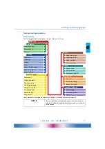
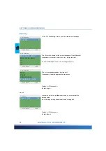
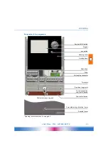
Main menu

Evaluation

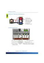
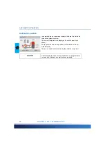
On the controller, you can make various settings and obtain 
information about states and processes.

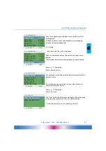
To this effect, press the knob in automatic mode.

›1 Main menu‹ appears.

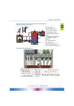
A list of subitems appears.

By turning the knob ...

...the lower part of the menu is displayed.

Select a subitem by pressing the knob.

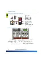
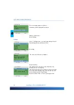
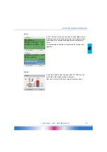
The ›1. Evaluation‹ menu provides information about the differ-
ential temperature controller smart Stove and the entire plant.

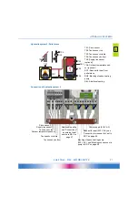
Select ›Measured values‹.

System 1

17.03.2016

10:14

1 Main Menu

17.03.2016

10:14

Evaluation

Settings
Basic functions
Monitoring
Login

1 Main Menu

17.03.2016

10:14

Settings
Basic functions
Monitoring
Login

About SmartStove

1.1 Evaluation

17.03.2016

10:24

Measured values

Service hours
Error list

Содержание smart Stove

Страница 1: ...G COMPANY OPERATING AND INSTALLATION INSTRUCTIONS DIFFERENTIAL TEMPERATURE CONTROLLER FOR ROOM SPACE HEATING SYSTEMS AND DOMESTIC HOT WATER SYSTEMS HANDLING SOLID FUEL HEAT SOURCES NAMELY WOOD LOG AND...

Страница 2: ...ions of these Assembly and Operating Instructions are the intellectual property of emz Hanauer GmbH Co KGaA Non authorized disclosure reproduction divulgation or editing of this documentation as well...

Страница 3: ...th zone valve 18 Connection of hydraulic system 2 18 Hydraulic system 3 Wood log stove tank with charging zones external domestic hot water tank 19 Connection of hydraulic system 3 19 Hydraulic system...

Страница 4: ...ion 31 Menu structure 31 Main menu 32 Evaluation 32 Settings 34 Basic functions 36 Monitoring 38 Login 38 About 39 System 39 Mounting 40 Dimensions 40 Opening the terminal cover 40 Wall mounting 41 De...

Страница 5: ...functions 67 Malfunction 73 Sensor monitoring 73 Service Wizard 74 Example for protective function 74 Example for malfunction 74 Replacement of fuse 78 Technical data 80 Differential temperature cont...

Страница 6: ...TABLE OF CONTENTS 6 smart Stove 0142 42WMSUGAT2 C Index 87...

Страница 7: ...ture controller smart Stove for solid fuel heat sources namely wood log and pel let stoves For operation of the entire plant the technical documentation of all the components used such as stove boiler...

Страница 8: ...sts The installer must have read and understood the operating manual The installer explains all the rel evant functions to the operator For operation it is essential that the housing is closed and fre...

Страница 9: ...rface wall see Mounting on page 40 For its own supply and the supply of the outputs the controller must be connected to an electrical energy supply system in accordance with the technical data see Ele...

Страница 10: ...ort provides access to the Micro SD card Only SD cards approved by the manufacturer must be used The controller automatically detects the Micro SD card Prior to removing the Micro SD card Rem SD card...

Страница 11: ...into calculation or presentation programs A new file will be created for each day The interval for data recording is 10 seconds The following values will be recorded and each row contains the followin...

Страница 12: ...knob and the esc button To find a required menu item turn the knob to scroll through the menu the selectable option appears on a coloured background on the display To confirm the selected menu item p...

Страница 13: ...pprox 10 Information screen During normal operation the information screen is displayed It shows the active system the system state the current temperatures and it animates active hydraulic components...

Страница 14: ...g the knob once When Separate mode is configured turning the knob will move the selection between space heating or domestic hot water The Common mode can be activated via Common Eco Comf during commis...

Страница 15: ...ation screen press the esc button Number and name of menu Professional mode Manual mode Message Check box Submenu arrow Selection menu Active menu item Scroll arrow Date and time 1 3 1 Thermostat R 17...

Страница 16: ...existing configuration The sensors are connected to TS1 to TS6 pumps and valves are connected to RO1 RO2 REL TS7 TS8 The interfaces are assigned to the functions in question on commissioning Supply l...

Страница 17: ...sensor optional RO1 Charging pump RO2 Blocking of space heating pump REL Additional heating TS6 TS5 RO2 TS1 TS2 TS3 TS4 RO1 REL Supply line sensor Outdoor temperature sensor Power supply 230 V AC Char...

Страница 18: ...sensor middle TS4 Tank sensor bottom RO1 Charging pump RO2 Zone valve REL Additional heating TS1 TS2 TS3 TS4 RO1 REL RO2 Tank sensor top Power supply 230 V AC Charging pump 230 V AC Tank sensor middle...

Страница 19: ...upply line sensor or out door temperature sensor optional RO1 Charging pump RO2 Zone valve REL Space heating pump TS8 Domestic hot water pump TS6 TS6 REL TS1 TS2 TS3 TS4 RO1 TS5 TS8 RO2 DHW tank senso...

Страница 20: ...1 Request for heat from pellet stove RO2 Blocking of space heating pump REL Additional heating TS6 TS5 RO2 TS1 TS2 TS3 TS4 RO1 REL Supply line sensor Outdoor temperature sensor Power supply 230 V AC R...

Страница 21: ...om pellet stove RO2 Blocking of space heating pump REL Additional heating TS6 TS5 RO2 TS1 TS2 TS3 TS4 RO1 REL Supply line sensor Outdoor temperature sensor Tank sensor middle Additional heating see Co...

Страница 22: ...r external additional heating RO1 Request for heat from pellet stove RO2 Additional heating pump REL Ext additional heating optional TS5 RO2 TS1 TS2 TS3 TS4 RO1 REL Sensor ext add heating Tank sensor...

Страница 23: ...e sensor optional RO1 Request for heat from pellet stove RO2 Zone valve REL Space heating pump TS8 Domestic hot water pump TS6 TS6 REL TS1 TS2 TS3 TS4 RO1 TS5 TS8 RO2 DHW tank sensor Optional sensor T...

Страница 24: ...mperature Charge start When the set value of DPD is reached the pump starts The dynamic pump delay can be set in professional mode see Basic functions on page 55 Dynamic pump control The charging pump...

Страница 25: ...ge 55 Overtemperature protection The temperatures of the stove and the tanks are monitored When overtemperature occurs at wood log stove the charging pump is forced to run At pellet stove the stove is...

Страница 26: ...D postpones the activation of the additional heating Before the addi tional heating is activated the dynamic recharge delay has to expire The dynamic recharge delay is calculated by the minutes degree...

Страница 27: ...ge blinking background on the stove symbol as an invitation to make fire With an little delay a buzzer will assist the request The buzzer can be enabled disabled optionally If fire is made in the stov...

Страница 28: ...ration mode under 1 3 1 Thermostat see Basic functions on page 36 Various thermostat and or timer functions can be defined Temperature thermostat Heating Temperature thermostat Cooling Timer function...

Страница 29: ...relay can also be driven inverted Combination of timer and thermostat Once at least one of these criteria is met the output is activated Any temperature difference to a reference sen sor will trigger...

Страница 30: ...ystem The current temperature is displayed for each temperature sensor Pump operation and valve position are illustrated on the ani mated display There is no need for intervention by the installer or...

Страница 31: ...ema or by the acti vated options Anti blocking Antifreeze protect Limits Error list Pump monitoring Sensor balancing Access code Manual mode Firmwareupdate SD Software version Hardware version Serial...

Страница 32: ...the lower part of the menu is displayed Select a subitem by pressing the knob The 1 Evaluation menu provides information about the differ ential temperature controller smart Stove and the entire plant...

Страница 33: ...s By scrolling down and actuating the menu item Reset all counters will be reset to zero Return to 1 1 Evaluation Select Error list The Error list shows all the error messages of the differential temp...

Страница 34: ...eviation or an extended period of de energizing If the differential temperature controller smart Stove is installed at a location where daylight saving time exists the time shift can be activated by A...

Страница 35: ...e set value to 10 Adjustable in the range from 30 to 255 seconds Activate Mirror system if you want to mirror the hydraulic scheme display Return to 1 2 Settings Select Buzzer Here you can disable or...

Страница 36: ...s for domestic hot water and space heat ing and enable additional heating if available The menu depends on the selected hydraulic system Select Thermostat The controller s free outputs can be used as...

Страница 37: ...onal heating When the buffer tank temperature falls below the Req add heat the dynamic recharge delay DRD time x temperature is started When the DRD is reached additional heating will be enabeled Scro...

Страница 38: ...he error message appears in plain text If necessary take the appropriate measures Return to 1 Main menu Select Login In order to enter the professional mode you must enter the access code See Settings...

Страница 39: ...ller smart Stove This information is required for repairs and for version man agement If no entry is made within the preset time 30 255 s on the smart Stove the display returns to System Use esc to re...

Страница 40: ...ensions Opening the terminal cover DANGER Electrical hazard Lethal danger due to electrocution Whenever work is performed on the open terminal cover all poles of the power supply must be disconnected...

Страница 41: ...nal cover carefully and protect it against damage To close the terminal cover reverse the opening procedure WARNING The device corresponds to protection type IP 20 Electrical hazard Make sure the appr...

Страница 42: ...g screw so that a space of 2 to 3 mm is created between the wall and the screw head 2 Move the device so that the upper fastening port is located above the screw head 3 and push it downwards 4 Fasten...

Страница 43: ...al cover on page 40 Knob with OK button Display esc button Housing cover Housing base Spare fuse Fuse Vortex plug connector Terminals Break out segments Screw connection strain relief device Strain re...

Страница 44: ...ents in the housing base can be removed carefully and the cables routed through these ports The central terminal block is the interface to a potential free change over contact here it may be necessary...

Страница 45: ...rt the strain relief Cable preparing NOTICE Before closing the terminal cover make sure the strain relief device is tightened safely Check once more that all cables are in good condition and connected...

Страница 46: ...Connection diagram for a zone valve without power supply to RO2 Connection diagram for a zone valve with power supply to RO2 Connection diagram for a zone valve without power supply to REL Connection...

Страница 47: ...REL Connection of a boiler to REL Connection of an external heat source to REL REL 11 14 12 L N PE L N PE Relay n c Attention Maximum switching capacity 230VA 11 14 12 Relay n o Attention Maximum swi...

Страница 48: ...request for heat to RO1 High efficiency pump A high efficiency pump can be connected via RO1 or RO2 The appropriate control signal is issued at TS7 TS8 The control signal may be an analog voltage 0 10...

Страница 49: ...been pro vided NOTICE High efficiency pumps are supplied with proportional or inverted control signals Only inverted for PWM control The pump type is selected during commissioning see page 51 RO1 or...

Страница 50: ...closed 0 1 Language appears after a short booting sequence Various languages are available in this version of the smart Stove Activate the required language by turning the knob and acknowledge it by...

Страница 51: ...etters and figures Do not change the file extension After selecting Next the graphic illustration of a hydraulic system is shown Scroll through all available hydraulic sc hem as by turning the knob se...

Страница 52: ...aulic scheme display i e the buffer tank will be displayed on the other side of the boiler Activate Mirror system if your plant is that way Note Mirror system does not influence the functions of the c...

Страница 53: ...activated for space heating and domestic hot water simultaneously By Fire Detection you can disable or enable fire detection for the stove see page 24 By Tank bottom sensor you can disable or enable...

Страница 54: ...vement of its efficiency To enter the professional mode select 1 7 Login from the main menu activate it and enter the access code The access code to professional mode is 365 The fact that the installe...

Страница 55: ...Output parameter Commissioning Anti legionellae Space heating Stop sensor The Thermostat Control parameters and Domestic hot water menus contain additional parameters Call up the menu item Thermostat...

Страница 56: ...ine switch ON OFF temperatures For the heating function T ON must be T OFF For the cooling function T ON must be T OFF In f PWM you define the PWM frequency In case a timer function has been selected...

Страница 57: ...start commissioning Commissioning on page 50 Return to 1 3 Basic functions Select Control parameters The menu depends on the selected hydraulic system System 1 Add heat enabled Recharging of the tank...

Страница 58: ...f zone valve Offset ZV act Temperature offset hysteresis for zone valve activation DPD Dynamic pump delay see page 24 High imm heater Force start and stop sensor to TS2 for additional heating This opt...

Страница 59: ...sis for additional heating pump Ext AH pump Off Switch off temperature offset hysteresis for additional heating pump fix PWM Fixed PWM speed of high efficiency pump for exter nal heat source System 7...

Страница 60: ...g Scroll down DRD DHW Eco Dynamic recharge delay for domestic hot water heating economy mode DRD DHW Comf Dynamic recharge delay for domestic hot water heating heating comfort mode Return to 1 3 Basic...

Страница 61: ...h stove With additional heating Req add heat Setpoint for request for heat from additional heating If the tank temperature falls below this temperature the request will be activated see page 27 Offset...

Страница 62: ...perature sensor for domestic hot water with additional heating in economy mode AH DHW Comf Temperature sensor for domestic hot water with additional heating in comfort mode Stove DHW Eco Temperature s...

Страница 63: ...Antifreeze protect NOTICE The antifreeze protection function may prevent the heating system from damage which could be caused by freezing medium Enter the lowest temperature Min temperature at which a...

Страница 64: ...ump monitoring observes the temperature change during the Monitoring time If the temperature does not change during this time the con troller releases an alarm Continue with Sensor balancing Long pipi...

Страница 65: ...flashes every second The new firmware is installed When installation is finished the controller reboots Continue with Manual mode In manual mode the individual outputs can be activated for testing pu...

Страница 66: ...update NOTICE Nothing should interrupt the update process especially no power loss NOTICE If the update has not begun within one minute after the selec tion of Firmwareupdate SD the controller will re...

Страница 67: ...for starting the loading pump x x x x x x x Charge offset 5 2 15 K Temperature offset for starting the speed control of the loading pump x x x Act ZV below 43 20 90 C Lower temperature threshold for a...

Страница 68: ...x x x x x Req add heat 50 20 90 C Setpoint for request for heat from stove with additional heat ing If the tank temper ature falls below this temperature the request will be acti vated x x x x x Offs...

Страница 69: ...or domestic hot water heating heating comfort mode x x x x x Anti legionellae x x x x x x x Activation Yes No Yes Activation of anti legi onella function x x x x x x x Target temp 60 55 85 C Target te...

Страница 70: ...eat ing x x x x x Offset SH block 2 1 10 K Temperature offset hysteresis for block ing space heating x x x x x Req add heat 50 20 90 C Setpoint for request for heat from addi tional heating If the tan...

Страница 71: ...ating in comfort mode x x x x x Stove DHW Eco TS 3 TS 3 TS 4 Temperature sensor for domestic hot water with stove in economy mode x x x x x x x Stove DHW Comf TS 3 TS 3 TS 4 Temperature sensor for dom...

Страница 72: ...2 42WMSUGAT2 C Stove SH Eco Comf TS 3 TS 3 TS 4 Temperature sensor for space with stove heating in comfort mode x x x x x x x Allow TS4 No No Yes x x x x x x x Menu parameter Default Range Unit Descri...

Страница 73: ...ce 1 931 The Attention symbol appears at the top right corner of the display A symbol indicates that there is a fault and the controller is in failure operation To start the Service Wizard press the k...

Страница 74: ...s only active until normal operation has been restored 1 10 Service Wizard appears The malfunction appears in plan text here M02 Breakage of sensor on TS1 If an analysis repair is not required at pres...

Страница 75: ...ir information appears Perform the appropriate repair work Exit the Service Wizard by pressing Exit f the cause of the malfunction has not yet been determined troubleshooting can be continued Continue...

Страница 76: ...screens After description of the troubleshooting measure the result determined by you is interrogated 1 10 Service Wizard 17 03 2016 12 14 Possible reasons Cable connection Sensor Exit 1 10 Service Wi...

Страница 77: ...n is made the repair work displayed After elimination of the malfunction the plant screen without the Attention symbol appears again on the display automatic mode is continued 1 10 Service Wizard 17 0...

Страница 78: ...a spare fuse are located Pull the upper part of the support and the spare part out The glass tube fuse is clamped in the formed piece and is removed together with the plastic holder DANGER Repair or d...

Страница 79: ...fuse laterally out of its holder The glass tube fuse is installed by reversing the above order Make sure to procure yourself immediately a new spare fuse DANGER Wrong fuse type used Risk of fire due t...

Страница 80: ...colour display 47 x 35 mm backlit Power reserve of real time clock at least h 8 Connection to power supply Design 3 spring type terminals PE N and L Operating voltage VAC 230 10 Line frequency Hz 50...

Страница 81: ...riac outputs RO1 RO2 Design 3 spring type terminals each PE N and L Output voltage VAC 230 10 Output power max per output VA 200 Output current max per output A 1 Switching output REL change over cont...

Страница 82: ...all poles of the power supply reliably and protect it them against being switched on again DANGER Loose cables Lethal danger due to electrocution When removing the controller secure all stripped cabl...

Страница 83: ...ot approved by the manufacturer Continued use of the controller despite an obvious defect Use of non approved spare parts and accessories Applications exceeding the intended scope of utilization Inapp...

Страница 84: ...arities The wood log or pellet stove with the differential temperature controller smart Stove has been installed and commissioned in an expert fashion The owner operator of the plant was informed in d...

Страница 85: ...e Software version Readings TS1 TS2 TS3 TS4 TS5 TS6 Wiring RO1 Pump HE Valve RO2 Pump HE Valve REL Yes No Service hours RO1 RO2 REL Equipment Accessories Options NOTICE For repair or replacement of th...

Страница 86: ...tage limits Directive 2004 108 EC of the European Parliament and the Council dated 15 December 2004 on harmonization of the laws of the Member States relating to electromagnetic compatibility and abol...

Страница 87: ...ommissioning report 84 Common mode 14 Communication screen 14 Components 43 Conditions of use 7 Connection 9 44 Control elements 12 Cooling 28 Cross sections of cables 80 D Data interfaces 10 Data log...

Страница 88: ...g 38 64 Mounting 9 40 O OK button 12 43 Opening 40 Operation 12 settings 31 Operation mode 13 Outdoor temperature sensor 16 Output parameter 55 56 Overtemperature protection 25 limits 64 P Parameters...

Страница 89: ...ftware version 39 Space heating 55 indication 13 Spare fuse 43 Stop sensor 55 Stove control 24 Strain relief device 43 Submenu 15 Summary of parameters 67 Supply line 16 System 13 39 choosing 51 T Tan...

Страница 90: ...Edition EN 03 2016 0142 42WMSUGAT2 C emz Hanauer GmbH Co KGaA Siemensstra e 1 D 92507 Nabburg Tel 49 0 9433 898 0 info emz hanauer com Fax 49 0 9433 898 188 www emz hanauer com...

Отзывы: