Emulex LP21000 Скачать руководство пользователя страница 8


LP21000 and LP21002 Hardware Installation Manual

Page 5

Applying Power

To apply power:

1. Verify that the CNA is securely installed in the computer.
2. Verify that the correct media is attached.
3. Plug in and turn on the computer.
4. Observe LEDs for Power On Self Test (POST) results.
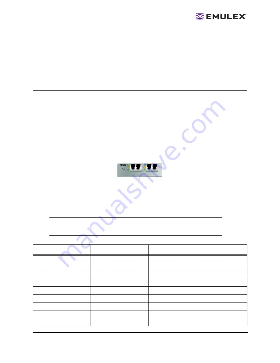
Viewing the LEDs

Green and yellow LEDs can be seen through openings in the CNA's mounting bracket. Each 
corresponding LED is summarized below:

10GbE Green (Ethernet Link)

ON Solid = Link up

ON/OFF Intermittent = Activity

OFF = No Link

Yellow (Adapter status; standard Emulex)

Green (Adapter status; standard Emulex)

Figure 2: CNA LED Indicators

POST Conditions and Results

POST (Power on Self Test) conditions and results are summarized in the following table:

Note: 

For the Fibre Channel Link Rate conditions, there is a 1 Hz pause when the LED is 

off between each group of fast blinks (1,2 or 3). You should observe the LED 
sequence for several seconds to ensure that the pause is correctly identified.

Table 3.  POST Conditions and Results 

Yellow LED

Green LED

State

Off

Off

Wake-up failure (Dead board)

On

Off

POST failure (Dead board)

Slow Blink

Off

Wake-up failure monitor

Fast Blink

Off

POST failure

Flashing

Off

POST processing in progress

Off

On

Failure while functioning

On

On

Failure while functioning

3 Fast Blinks

On

4Gb Link rate-Normal, link up 

Off

Slow Blink

Normal-link down or not started

Содержание LP21000

Страница 1: ...LP21000 and LP21002 CNA Installation Manual Last updated September 19 2008 Critical Connectivity SolutionsTM...

Страница 2: ...are registered trademarks and AutoPilot Manager Critical Connectivity Solutions EZPilot SLI and VMPilot are trademarks of Emulex All other brand or product names referenced herein are trademarks or r...

Страница 3: ...duction 1 Major Features 1 Compatibility 2 Prerequisites 2 Installing the Converged Network Adapter 3 Attaching Media 4 Applying Power 5 Viewing the LEDs 5 POST Conditions and Results 5 Typical EE Con...

Страница 4: ...fferent models LP21000 M single port with Optics LP21002 M dual port with Optics LP21000 C single port with Copper LP21002 C dual port with Copper Single 8 lane standard Gen 1 PCIe interface shared by...

Страница 5: ...e supported by Solaris Prerequisites PCI Express 1 0a compliant systems x8 lane transfer link interface at 2 5 Gb s per lane Single 8 lane standard Gen1 PCIe slot is required for operation Table 1 Sof...

Страница 6: ...rs before installation 2 Turn off and unplug the computer 3 Remove the computer case 4 Remove the blank pane from an empty PCIe bus slot bus slot Follow steps 5 8 to change the brackets if they are di...

Страница 7: ...following specifications To attach media to the CNA 1 Connect the cable to the LC connectors on the CNA 2 Connect the other end of the cable to a Top of Rack TOR EE switch See figure 1 Figure 1 Conne...

Страница 8: ...Figure 2 CNA LED Indicators POST Conditions and Results POST Power on Self Test conditions and results are summarized in the following table Note For the Fibre Channel Link Rate conditions there is a...

Страница 9: ...Page 6 Slow Blink Slow Blink Off line for download Fast Blink Slow Blink Restricted off line mode Waiting for restart Flashing Slow Blink Restricted off line mode Test active Table 3 POST Conditions...

Страница 10: ...Typical EE Configuration Diagram 1 2 CNAs Figure 3 Typical EE Configuration Diagram 1 2 CNAs Server Requirements Visit http www emulex com support or contact Emulex Corporation with any questions or c...

Страница 11: ...er single dual port 10 Gigabit optical fiber or copper LC connectors to the Enhanced Ethernet Physical Dimensions Standard PCIe form factor PCBA full height 9 1 Power Requirements Dual Port 25 Watts S...

Отзывы: