background image

Selecting a Tool-Offset: (Continued…)

.

.

IN  TOOL

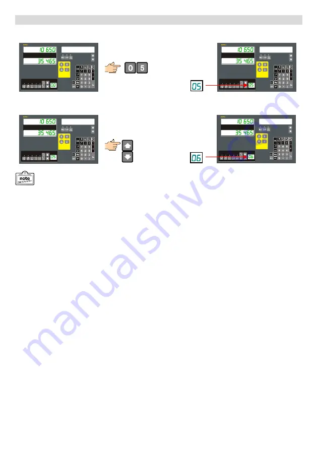
There is no need to press the enter key as
we are in Tool use mode.

.

.

IN  TOOL

The desired Tool Offset can be selected using the Tool navigation keys or by typing the desired tool number in
directly using the numeric keypad.

Example: Select Tool #5

All normal functions such as Axis Summing, axis preset etc. continue to operate in Tool Offset mode.

.

.

IN  TOOL

Example: Move from Tool #5 to Tool #6

.

.

IN  TOOL

- 16 -

Содержание EM250 Series

Страница 1: ... Professional Digital Readout System for Manually Operated Machine Tools EMS International Limited Brookfield Works Canal Street Littleborough Lancashire OL15 0HA England Telephone 44 0 116 279 3035 e mail info ems i co uk web www ems i co uk ...

Страница 2: ......

Страница 3: ...d 10 Shrink Function 11 Reference Function 11 Calculator 12 Lathe Functions 13 Radius Diameter mode 13 Axis Summing 13 Lathe Tool Offsets 14 Milling Functions 17 Work to Zero 17 Sub datums SDM 17 PCD Pitch Circle Diameter Bolt Hole 21 Line Hole Function 23 Inclined Machining 25 Machining a Radius 28 Setting the Z Step Method 28 Simple Radius Function R Function 29 Enhanced Radius Function Auto R 3...

Страница 4: ...ry If you would like to make any comments or share your experience of using our equipment we would very much like to hear from you Please e mail us at info ems i co uk Note Please familiarize yourself with the contents of thus operators manual before installing the DRO to ensure a easy installation Due to a process of continual development EMS International Ltd reserve the right to change specific...

Страница 5: ...h or nearby high capacity switching inductive load or where it can cause danger Avoid routing cables with those of the motor lighting or other such sources of potential RF and electrical noise Please Read Before Proceeding Warranty will be considered void if and not limited to Failing to meet manufacturers specified supply conditions Abusive handling Environmental conditions outside of Manufacture...

Страница 6: ...ws EXIT Release Number key The Setup options vary slightly between Lathe and Mill DRO Function This function is used on 2 axes Mill DRO s by the Inclined machining and Arc contouring functions to simulate a Z axis input by calibrating the DRO to the resolution and turns of the Knee axis dial Operation Press the key The message display will show ENTR PPM Enter the distance moved by the Z axis for o...

Страница 7: ... used to reset the DRO to its factory default settings Any changes made will be lost and need to be re entered Operation Press the key Wait until CLR OK is displayed Display shows ALL CLR Function This function is used on 2 axes Mill DRO s by the Inclined machining and Arc contouring functions to simulate a Z axis input by calibrating the DRO to the resolution and turns of the Knee axis dial Opera...

Страница 8: ...coder by a constant factor in PPM Parts Per Million microns meter Example Scale measures 500 040 True measurement is 500 000 error 0 080mm over 1m or 80PPM Operation Press the key to enter the function The axes windows will display the current settings Press the axis key for the axis you want to change e g Enter the value using the numeric keys You can change the sign of the compensation using the...

Страница 9: ... top slide can be rotated from parallel to the X axis to parallel with the Z axis through any angle This is known as the compound or Z axis See axis Summing later in this manual With milling machines we have the X Y and Z axis The X Y axis refer to the table movement left right and in out The Z axis can be either the Quill axis direct movement of the tool up down or the Knee axis which is the move...

Страница 10: ... those machine types to be readily available whilst not overcomplicating the display keypad with buttons you will never use Quick axis zero keys Axis Set keys Axes Position Windows Tinted Message Window Navigation Keys Special Function Keys Calculator keys Calculator Memory Parameter Enter Key Half Function Clear Value Tool Point Display Function Keys Tool Point Selection Wipe Clean Membrane Tacti...

Страница 11: ...before metrication Equally many drawings from the United States are in Imperial measurement units All axes are effected by this operation ABS Example Switch from mm to Inch mode ABS As there are 25 400mm per Inch due to the limitations of any given display resolution some rounding of the conversion may result Common Functions This section goes through the functions that are common between the Lath...

Страница 12: ...n allows for an incorrectly entered value to be cleared so that a correct value can be entered ABS NEW BASE Example Set X axis value to 16 05 NEW BASE NEW BASE New value can now be entered as above Half Function Centre Find This function is used to find the centre of a work piece by halving the displayed distance on the selected axis INC AXIS 1 2 Example Find the Centre of X axis INC Move the axis...

Страница 13: ...hat the same reference is used every time This can be the first reference from one end of travel or alternatively by always starting the reference search from the same physical machine position Shrink Function This function key allows for the programming of a scalar value that can be used to compensate for part shrinkage Whilst it can be used on Lathe DRO s it is primarily intended for use when ma...

Страница 14: ...e transferred back in to a chosen axis ABS Enter the DRO Calculator The axes values are still displayed Add Subtract 53 12 9 56 Examples Use Trig 100 COS 30 86 60254 Use Inverse Trig Sin 0 5 30o Use X axis value 25 4 x 3 76 2 Transfer Value offset to X axis X 25 4 Value 45 465 So in order to get to position 45 465 we need to move 25 400 45 465 20 065 Move axis to 0 000 to get to 45 465 relative to...

Страница 15: ...nctions to assist in turning These functions are described in more detail in this section Lathe Functions Radius Diameter mode Generally on a lathe we want to operate the cross slide X axis in Diameter mode as that reflects on the dimensions of the part being turned The mode can be quickly changed by pressing the key The operating display mode is shown by the status of the associated LED INC ABS E...

Страница 16: ...0 5mm for Tool 1 TOOL FUN Use the Tool navigation keys TOOL FUN Note that any previously set offset will be shown so may not be 0 000 IN OFFST Tool number now shown in Tool display How to define a Tool Offset Each tool will have its own offset and must be re calibrated in the event of wear or where it has to be replaced due to breakage The EM250 stores Tool Offsets for the X Axis only In order to ...

Страница 17: ...UN ABS The last Tool is shown in Tool display and is actively being applied Turn Off Tool Offsets To turn off Tool Offsets you can either use the tool navigation keys to Tool or by simply pressing the key ABS ABS If a value is shown other than in the Tool display then that Tool Offset value is being applied Selecting a Tool Offset ABS IN TOOL Tool Offsets are now operational but not yet applied as...

Страница 18: ...The desired Tool Offset can be selected using the Tool navigation keys or by typing the desired tool number in directly using the numeric keypad Example Select Tool 5 All normal functions such as Axis Summing axis preset etc continue to operate in Tool Offset mode IN TOOL Example Move from Tool 5 to Tool 6 IN TOOL 16 ...

Страница 19: ...art looking at the functions in depth it is worth noting that the EM250 DRO like all DRO operates on a principle within functions known as Work to Zero Normally you may expect to zero an axis display and move to a number of your choosing and for simple operations this is OK However as tasks get more complicated it is easier for the DRO to display the distance the tool is currently away from the de...

Страница 20: ...MODE Select SDM 3 zero the axes and in so doing define the offset co ordinate of SDM 2 SDM MODE Still on SDM 3 move to the desired SDM 3 co ordinate SDM MODE SDM MODE SDM MODE Select SDM 4 zero the axes and in so doing define the offset co ordinate of SDM 3 SDM MODE Still on SDM 4 move to the desired SDM 4 co ordinate SDM MODE SDM MODE SDM MODE Select SDM 5 zero the axes and in so doing define the...

Страница 21: ...e been entered you can now start using them straight away As long as the Message window is displaying the text SDM MODE the axis displays are showing the current position of the tool from the SDM co ordinate as displayed in the SDM window This direct entry of SDM co ordinates is particularly useful when working on batch jobs or where centre or origin co ordinates of features to be machined can be ...

Страница 22: ...sable SDM mode ABS SDM MODE Example Select SDM 5 ABS SDM MODE Method 2 Direct SDM selection The values in the axis will reflect the current offset from zero for the selected datum Above is only an example Disable SDM Mode The SDM mode is automatically disabled if SDM 0 is selected However it is more common to simply re press the SDM key e g SDM MODE ABS 20 ...

Страница 23: ...e circle Diameter of the circle Number of holes required Start angle of the first hole End angle of the last hole X Y Angles are positive clockwise 1 To best demonstrate these methods let us consider the part below as by way of example Parameter Value Centre co ordinates 0 000 0 000 Diameter 80mm Number of Holes 5 Start Angle 30o End Angle 300o If a full circle is needed Start Angle 0o End Angle 3...

Страница 24: ...dow will show the current selected Hole number and the X and Y axis will show the offset to the centre of that hole By moving the axes until they are both showing you will now be at the calculated hole centre Navigate between holes using the Message navigation keys HOLE 2 HOLE 1 Check ABS position whilst in PCD Function If at any time whilst in the PCD function you would like to check the standard...

Страница 25: ...X Y Angles are positive clockwise To best demonstrate these methods let us consider the part below as by way of example Parameter Value Length of Line 80mm Angle of Line 30o Number of Holes 4 ABS LIN DIST Move to the position of the first hole in the line and then enter the Line Hole function by pressing the key The key LED will be illuminated showing the function is now active LIN DIST Enter the ...

Страница 26: ... the X and Y axis will show the offset to the centre of that hole By moving the axes until they are both showing you will now be at the calculated hole centre Navigate between holes using the Message navigation keys HOLE 2 HOLE 1 Check ABS position whilst in the Line Hole Function If at any time whilst in the Line Hole function you would like to check the standard ABS position relative to the work...

Страница 27: ...0 5mm 30o 0 5mm The finer the step the smoother the finish ABS Move the tool to the start position of the incline to be machined You may wish to set this as a datum but it could be any value or even an SDM point Then enter the function using the key INCL XY Navigate to the required plane INCL YZ INCL XZ Use the Message Navigation keys In this example in order to machine a 30o angle for every 0 5mm...

Страница 28: ...e first machining Point with the X Y axis displays left aligned to indicate that it is operating in a special mode PT 1 Move the X axis and Y axis to Then press the key to move to the next next point and repeat the process until the ARC machining operation is completed You can navigate through the points using the keys PT 1 PT 2 PT 2 PT 3 The following is only required for the XY Plane 2 axis and ...

Страница 29: ...n the angle of cut The following is the operating mode on XZ ZY Plane on 3 axes DRO The DRO will simulate a Z axis position based on the DIAL INC and Z DIAL values configured in Setup It is the operators responsibility to move the dials as per the DRO display Z Move X axis to zero and then move the Z axis When you have moved the Z axis use the message navigation keys to inform the DRO that the mov...

Страница 30: ...d to be entered for which the operator may need to do some calculations Setting the Z Step Method The EM250 allows for two methods of operation for controlling the finish of the ARC being machined and this is controlled by the key If we consider the XZ plane then as we move around an ARC the rate of change in Z increases for a consistent change in Z Thus in order to get a smooth finish the DRO can...

Страница 31: ...Position tool at the start of the arc Move the Tool to the start of the ARC It is also possible to machine in the Z plane on a 2 axes XY DRO on Mills To do this we will need to use the Knee axis Z dial for as a manual reference ABS SIM R XY Navigate to the plane required and press key The display will move to the ARC type entry automatically SIM R XZ TYPE 1 8 Set the Z STEP to the required machini...

Страница 32: ...uired ARC type with reference to the ARC Table TYPE 1 8 R TOOL R TOOL The following parameters may not appear on ALL plane selections DRO types 2x 3x MAX CUT MAX CUT R TOOL Navigate to the Tool compensation entry and enter the Tool Cut edge Next set the MAX CUT value R TOOL The EM250 will use this as the maximum step value and automatically calculate the best possible axis increment according to t...

Страница 33: ...r the XY Plane 2 axis and 3 axis DRO The execution of the function varies between 2 axes and 3 axes DRO for the YZ XZ planes as we have to use the Z dial calibration performed in Setup to simulate the Z axis on 2 axes DRO systems The DRO will simulate a Z axis position based on the DIAL INC and Z DIAL values configured in Setup It is the operators responsibility to move the dials as per the DRO di...

Страница 34: ...il the X axis shows This process can be repeated until the inclined machining operation is completed AUTO XZ AUTO XZ AUTO XZ AUTO XZ If the message window displays Z OU LI it means that the Z axis is outside of the line of the calculated ARC AUTO XZ AUTO XZ AUTO XZ Check ABS position whilst performing R Function Machining ALL DRO If at any time whilst in the R Function you would like to check the ...

Страница 35: ... Z 0 000 ARC End X 40 000 Z 20 000 Tool Diameter 6mm Tool Compensation R Max Step 0 3mm Set the Z STEP to the required machining mode using the key BEFORE entering the R Function To best demonstrate these methods let us consider the part below as by way of example Move the Tool to the start of the ARC It is also possible to machine in the Z plane on a 2 axes XY DRO on Mills To do this we will need...

Страница 36: ...he ARC and press XZ CENT R Navigate to the ARC Radius entry and enter the required value and press R XZ ST PT Navigate to the ARC Start entry and enter the required value XZ ST PT XZ END P Navigate to the ARC end entry and enter the required value XZ END P On 2 axes Mill the Z axis entry is made in to the Y axis TOOL DIA Navigate to the Tool Diameter entry and enter the required value TOOL DIA 34 ...

Страница 37: ... The EM250 will use this as the maximum step value and automatically calculate the best possible axis increment according to the curvature of the ARC to be approximately equal to the MAX CUT value Once all the parameters have been entered you can check them by going back through them using the navigation key Alternatively you can also start using the function immediately by pressing the key once m...

Страница 38: ...simulate a Z axis position based on the DIAL INC and Z DIAL values configured in Setup It is the operators responsibility to move the dials as per the DRO display Z 0 500 Z 0 250 Move X axis to zero and then move the Z axis When you have moved the Z axis use the message navigation keys to inform the DRO that the movement has been completed and move to the next point This process can be repeated un...

Страница 39: ...l the X axis shows This process can be repeated until the inclined machining operation is completed AUTO XZ AUTO XZ AUTO XZ AUTO XZ If the message window displays Z OU LI it means that the Z axis is outside of the line of the calculated ARC AUTO XZ AUTO XZ AUTO XZ Check ABS position whilst performing R Function Machining ALL DRO If at any time whilst in the R Function you would like to check the s...

Страница 40: ...er to the axes such that the machined part id oversize by a set amount Most useful when machining mould tools This key is used to confirm a selection Used in set functions such as setting a reference Not the same as Ent This is the main ENTER key and used for confirming entry of all main parameters such as setting an axis value This is navigation key by the message window and is used to move betwe...

Страница 41: ...ng 3 axes DRO only Toggle display between Radius and Diameter mode Used to enable disable Tool offset mode Mill Functions Lathe Functions Key Description Bolt hole PCD calculator function Line hole function Inclined Machining function Arc machining function Arc machining step size Simplified arc machining function Setting of sub datums or auxiliary co ordinates to aid multiple operations on a sing...

Страница 42: ...and the LED displays It also puts the DRO under maximum current load As such if there is an issue with the DRO supply the DRO will most likely have an issue during this process If this occurs please consult the Troubleshooting section for assistance EM250 Models The EM250 DRO is available in 4 versions each machine type specific 2 axes Lathe 3 axes Lathe 2 axes Milling 3 axes Milling ems i have a ...

Страница 43: ...e system Add the equipotential connection from the DRO to the Machine body Ensure encoder cables are not close to drive or lighting cables that can be electrically noisy Vibration in brackets can also be a cause so check all mountings are tight and free from play Connect to a different power socket or if connected to a machine supply try connecting to a standard wall socket with an IEC lead Axis i...

Страница 44: ...EMS International Limited Brookfield Works Canal Street Littleborough Lancashire OL15 0HA England Telephone 44 0 116 279 3035 e mail info ems i co uk web www ems i co uk ...

Отзывы: