background image

37873-0-0217

Page 24

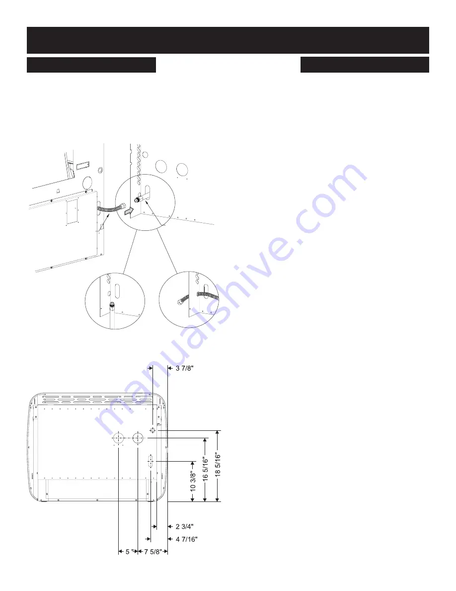
Tuyau d’alimentation en gaz à l’appareil de chauffage mural

1. 

Tirer le tuyau de gaz souple installé à l’usine à travers l’orifice du 

panneau arrière. 

Voir Figure 36.

2.  Raccorder le tuyau d’alimentation en gaz au tuyau de gaz 

souple.  Vérifier  que  le  tuyau  souple  n’est  pas  plissé  après  son 

raccordement  au  tuyau  d’alimentation  en  gaz. Tout  excédent  de 

tuyau souple peut être repoussé dans l’appareil. 

Voir Figure 36.

Figure 36

Figure 37 

ALIMENTATION EN GAZ

INSTALLATION DE L’APPAREIL DE CHAUFFAGE MURAL

TUYAU FLEXIBLE

TUYAU 

D’ALIMENTATION 

EN GAZ (PAR 

INSTALLATEUR)

INSTALLATION POSSIBLE DU TUYAU 

DE GAZ À TRAVERS LE PLANCHER

INSTALLATION POSSIBLE DU TUYAU 

DE GAZ À TRAVERS LE CÔTÉ

Содержание PVS18N-3

Страница 1: ...rence Attention Checklocalcodesforventingrequirements Young children should be carefully supervised when they are in the same room as the appliance If installed in a direct vent application this appli...

Страница 2: ...17 Wall Furnace Display 18 Wall Furnace Component Arrangement Front 19 Wall Furnace Component Arrangement Rear 20 Wall Furnace Installation 21 38 Mounting the Rear Shroud 21 22 Gas Supply 23 24 Vent...

Страница 3: ...and circulating air passageways of the appliance be kept clean DO NOT put anything around the appliance that will obstruct the flow of combustion and ventilation air DO keep the appliance area clear a...

Страница 4: ...as can adsorb or absorb onto or into walls masonry and other materials and fabrics in a room That will take some of the odorant out of the gas reducing its odor intensity LP Gas may stratify in a clos...

Страница 5: ...tified 3 SIGNAGE A metal or plastic identification plate shall be permanently mounted to the exterior of the building at a minimum height of eight feet above grade directly in line with the exhaust ve...

Страница 6: ...led must be electrically ground ed in accordance with local codes or In the absence of lo cal codes in Canada with the Canadian Electrical Code CSA C22 1 and in the United States with the National Ele...

Страница 7: ...37873 0 0217 Page 7 OWNER S MANUAL AND OPERATION INSTRUCTIONS www empirezoneheat com...

Страница 8: ...o the unit is on The shutoff valve should be in the OPEN position See Figure 4 CLOSED OPEN Figure 4 Starting the Wall Furnace The wall furnace has three modes for controlling operation Remote Manual a...

Страница 9: ...Local thermostatic mode press the Mode Select button on the wall furnace display panel three times from the off mode The display panel will show the current room temperature See Figure 8 Figure 8 Not...

Страница 10: ...If operating in Local mode the heat level will adjust automatically 4 The red and green control panel LED lights will begin to flash alternately while the wall furnace performs a safety test After app...

Страница 11: ...to operate from 100 to 160 seconds to ensure the wall furnace cools off Power Interruption The wall furnace requires a 115VAC power source to operate See Specifications on page 16 When power is resto...

Страница 12: ...es will require the system to be reset To reset the wall furnace press the mode selection button on the display panel repeatedly until the wall furnace cycles through the OFF setting once If the error...

Страница 13: ...37873 0 0217 Page 13 INSTALLATION INSTRUCTIONS www empirezoneheat com...

Страница 14: ...rried to the condensate trap resulting in a clog An A2 error will appear on the display panel if this happens The clog and the work required to fix it can be eas ily prevented by pulling a wet cloth t...

Страница 15: ...ad of gravity drain PVSCT10 Condensate Hose Extension 10 ft condensate drain extension CONTROLS Part Number Description Features PVSRT1 Temperature Sensor Relocation Kit Room Temperature Sensor Extens...

Страница 16: ...e 50 feet maximum equivalent length See pages 26 and 29 to 32 The vent termination elbow does not contribute to the overall vent length measurement Input ratings are based on sea level operation and m...

Страница 17: ...clearances from casing to combustible construction are 12 305mm on top 0 0mm on each side and 0 0mm from the floor 0 0mm to rear wall and36 914mm infrontofthewallfurnacetowallsorfurniture Notice It is...

Страница 18: ...t will disappear when the room temperature is displayed RESET Shows when heater needs to be reset Blower Icon Shows when room air blower is running C F Changes temperature units from Fahrenheit to Cel...

Страница 19: ...FF SWITCH BURNER COMPARTMENT GAS VALVE GAS VALVE ON OFF SWITCH CIRCULATING AIR BLOWER INDUCER INDUCER MOTOR HEAT EXCHANGER FRONT SHIELD INNER SHIELD SINGLE TUBE UNITS ONLY FRONT LOUVER ASSEMBLY DISPLA...

Страница 20: ...ON AIR INTAKE TEMPERATURE SENSOR FLUE OUTLET DISPLAY PANEL FILTER COVER REAR SHROUD COMBUSTION AIR INTAKE DIRECT VENT FLUE OUTLET GAS LINE OPENING ALTERNATE GAS LINE OPENINGS ALTERNATE ELECTRICAL CORD...

Страница 21: ...the bottom of the unit if necessary See Figure 29 Figure 29 Use masking or painter s tape to mark the location of the two top corners of the rear shroud against the wall See Figure 30 Figure 30 Move...

Страница 22: ...nst the wall and secure in place The shroud should be mounted to the wall studs if possible using the four 10 x 1 1 2 hex head screws provided Two screws in top holes and two screws in bottom holes Se...

Страница 23: ...d on each joint or union using a small paintbrush If any bubbling is observed the connection is not sealed adequately and must be retightened Repeat the tightening and soap check process until the bub...

Страница 24: ...ory installed flexible gas line through the hole in the back panel See Figure 36 2 Connect the gas supply line to flexible gas hose Ensure that flexible gas hose is not kinked after fitting gas supply...

Страница 25: ...tance of 2 feet 61 cm from the center line of the terminal 12 in 30cm 12 in 30cm L Clearance above paved sidewalk or paved driveway located on public property 7ft 2 13m 7ft 2 13m E Clearance to unvent...

Страница 26: ...he vent system will be the equivalent to 3 feet and each 45 elbow is equivalent to 1 5 feet which should be added to the overall vent length 1 The installation must conform with as applicable A A non...

Страница 27: ...Armaflex type insulation or equivalent Ameraflex is a regis tered trademark of Amaracell Insulating pipe is important to avoid condensate icing See Figure 39 Figure 39 The minimum flue length off the...

Страница 28: ...wn Eliminate all sags or dips as they may prevent drainage An optional drain tube extension kit and optional condensate pump kit accessory are available See page 15 Notice Due to the mildly acidic nat...

Страница 29: ...w installed the length of the run MUST be reduced by 1 5 feet 45 cm Reduce the length of the run three feet 91 4 cm for every 90 elbow The vent terminal elbow does not contribute to the overall vent l...

Страница 30: ...to 7 12 15 381 mm Over 7 12 to 8 12 18 457 mm Over 8 12 to 16 12 24 610 mm Over 16 12 to 21 12 36 914 mm Figure 49 Single Flue Vertical Vent Run WARNING Major U S building codes specify minimum chimn...

Страница 31: ...90 elbow both pointed downward Notice All horizontal runs require a 1 4 per foot rise to run con densation back to the wall furnace Notice For each 45 elbow installed reduce the length of the run MUS...

Страница 32: ...ation The total horizontal vent length of the flue system is 14 feet and the total vertical length is 30 feet The two 90 elbows are equivalent to six feet bringing the total to 50 feet Notice For vert...

Страница 33: ...formation above 2 Open bottom louver assembly or open the service ac cess panel 3 Turn off all electric power to the appliance 4 Turn gas line valve to OFF 5 Close bottom louver assembly or close serv...

Страница 34: ...to the black wire The wall furnace will not operate properly unless the polarity and ground are correct WIRING WALL FURNACE INSTALLATION Optional Controls WARNING Potential risk of fire electric shoc...

Страница 35: ...UNE WHITE BLANC BLACK NOIR RED ROUGE RED ROUGE BLACK NOIR RED ROUGE RED ROUGE BROWN BRUN BLUE BLEU BLUE BLEU BROWN BRUN BLACK NOIR WHITE BLANC WHITE BLANC GREEN VERT BLACK NOIR BLUE BLEU BLUE BLEU BLU...

Страница 36: ...e points proceed to lighting instructions Refer to Page 33 Notice Verify any kits are installed per the instructions included with the kit STARTUP CHECK LIST Paint Curing First Firing The UltraSaver h...

Страница 37: ...he inducer will activate and perform a safety test lasting 45 seconds The ignition sequence will initiate after this test 3 The Hot Surface Ignitor will start to glow red 4 After 20 seconds the gas va...

Страница 38: ...at to a set ting below the room temperature or push the display panel s mode select button to OFF See Figure 15 page 11 DO NOT cut the main electrical power to the wall furnace The circulating air blo...

Страница 39: ...cation Tray accessory kit check that the tray is level and functioning Red LED permanently ON Green LED performs two blinks followed by a one second pause Transducer fault A3 Yellow LED permanently OF...

Страница 40: ...ely and efficiently Should you suspect any abnormal operation contact a service person that has been trained to service this product MAINTENANCE FOR THE HOMEOWNER Removing the Front Panel It may becom...

Страница 41: ...o below freezing temperatures the condensate system water trap will need to be winterized to prevent damage to the wall furnace 1 Remove the front cover assembly by carefully lifting up and then pulli...

Страница 42: ...R11605 HOT SURFACE IGNITOR 36 R2543 FLAME SENSOR 37 R11644 LIMIT SWITCH EXCHANGE 38 R10961 FLEX LINE 39 R11607 VIEWING WINDOW 41 R11606 MANIFOLD GROMMET 42 31569 BURNER MANIFOLD SUPPORT BRACKET 43 R11...

Страница 43: ...37873 0 0217 Page 43 EXPLODED VIEW 7 17 5 6 3 2 18 4 12 23 19 21 27 26 24 25 20 15 14 16 28 29 32 30 31 22 43 42 45 36 39 40 27 33 34 44 41 35 38 1 13 37 46 29 47 49 48 50...

Страница 44: ...se and can be ordered by your Service Person or Dealer Proof of purchase is required for warranty parts All parts listed in the Parts List have a Part Number When ordering parts first obtain the Model...

Страница 45: ...37873 0 0217 Page 45 APPLIANCE SERVICE HISTORY Date Dealer Name Service Technician Name Service Performed Notes...

Страница 46: ...37873 0 0217 Page 46 APPLIANCE SERVICE HISTORY Date Dealer Name Service Technician Name Service Performed Notes...

Страница 47: ...at Empire s option Duties Of The Owner The appliance must be installed by the selling dealer or his designated installer and operated in accordance with the instructions furnished with the appliance...

Страница 48: ...ww empirecomfort com Empire Comfort Systems Inc Belleville IL If you have a general question about our products please e mail us at info empirecomfort com If you have a service or repair question plea...

Страница 49: ...gences de ventilation Les jeunes enfants doivent tre surveill s avec attention lorsqu ils sont dans la m me pi ce que l appareil Dans une installation ventilation directe tuyauterie double cet apparei...

Страница 50: ...age mural Avant 19 Position des composants de l appareil de chauffage mural Arri re 20 Installation de l appareil de chauffage mural 21 38 Montage du capot arri re 21 22 Alimentation en gaz 23 24 D ga...

Страница 51: ...r de l appareil susceptible d obstruer la circulation d air de combustion et de ventilation Maintenir la zone autour de l appareil d gag e et exempte de mati res combustibles essence et autres vapeurs...

Страница 52: ...nt pr sent dans le gaz chapp peut tre adsorb ou absorb dans les murs la ma onnerie et autres mat riaux ou tissus dans la pi ce Cela r duit la quantit d odorisant dans le gaz et donc l intensit de l od...

Страница 53: ...ique devra tre appos e en permanence l ext rieur du b timent une hauteur minimale de huit pieds au dessus du sol directement en ligne avec la bouche d vacuation de l appareil ou l quipement de chauffa...

Страница 54: ...ent reli la terre en conformit avec la r glementation locale Ou en l absence de r glementation locale il soit respecter le Code canadien de l lectricit CSA C22 1 au Canada ou le National Electrical Co...

Страница 55: ...37873 0 0217 Page 7 GUIDE D UTILISATION ET INSTRUCTIONS D INSTALLATION www empirezoneheat com...

Страница 56: ...appareil est ouverte Le robinet d arr t doit tre la position OUVERT Voir Figure 4 CLOSED OPEN Figure 4 D marrage de l appareil de chauffage mural L appareil de chauffage est dot de trois modes pour co...

Страница 57: ...Mode Local Thermostat int rieur 1 Pour contr ler l appareil de chauffage en mode Local thermostatique appuyer trois fois sur le bouton Mode Select du panneau d affichage depuis le mode Arr t Off Le p...

Страница 58: ...mode Manuel Si l on se trouve en mode Local le niveau de chaleur se r glera automatiquement 4 Les t moins rouge et vert du panneau de commande commenceront clignoter en alternance pendant que l appare...

Страница 59: ...reil Interruption de courant L appareildechauffagen cessiteunesourced alimentationde115Vc a pour fonctionner Voir les Caract ristiques techniques la page 16 Unefoislecourantr tablisuite uneinterruptio...

Страница 60: ...erl appareil appuyer r p titionsurleboutondes lection de mode du panneau de commande jusqu ce que l appareil d file par le r glage OFF arr t une fois Si l anomalie a t corrig e l appareil de chauffage...

Страница 61: ...37873 0 0217 Page 13 INSTRUCTIONS D INSTALLATION www empirezoneheat com...

Страница 62: ...nsat est con u pour s couler vers l appareil ces d bris seront vidang s dans la trappe condensat et causeront une obstruction Une anomalie A2 s affichera sur le panneau d affichage si cela se produit...

Страница 63: ...t ext rieure Pompe le condensat l cart de l appareil de chauffage plut t qu une vidange par gravit PVSCT10 Rallonge de tuyau de condensat Rallonge de tuyau de vidange du condensat de 3 m 10 pi COMMAND...

Страница 64: ...oude terminal ne compte pas dans le calcul de la longueur totale de la tuyauterie de ventilation Les valeurs d admission sont bas es sur un fonctionnement au niveau de la mer et peut varier diff rente...

Страница 65: ...e dessus 0 mm 0 po de chaque c t 0 mm 0 po depuis le plancher et 914 mm 36 po devant l appareil jusqu aux murs et l ameublement Avis Il est recommand de laisser un d gagement de 203 mm 8 po de chaque...

Страница 66: ...e Bascule entre les modes Arr t Distant Manuel Local AUX S affiche durant le fonctionnement du plateau chauffant en accessoire R tro clairage Active le r tro clairage de l cran Affiche aussi la temp r...

Страница 67: ...FRONT COVER ASSEMBLY CONDENSATE TRAP AIR PRESSURE TRANSDUCER PRESSURE SWITCH Figure 25 PANNEAU D AFFICHAGE BO TIER EXT RIEUR PANNEAU FRONTAL VENT LAMES SOUFFLANTE DE CIRCULATION D AIR MOTEUR DE SOUFF...

Страница 68: ...E DIRECT VENT FLUE OUTLET GAS LINE OPENING ALTERNATE GAS LINE OPENINGS ALTERNATE ELECTRICAL CORD OPENING PANNEAU DU FILTRE PANNEAU D AFFICHAGE SONDE DE TEMP RATURE CAPOT ARRI RE ORIFICE D VACUATION OR...

Страница 69: ...29 Figure 29 Utiliser du ruban cache pour marquer l emplacement des deux coins sup rieurs du capot arri re contre le mur Voir Figure 30 Figure 30 D placer l appareil de chauffage l cart du mur et enl...

Страница 70: ...en place Le capot doit tre mont sur les montants muraux si possible l aide des quatre vis t te hexagonale 10 x 1 1 2 po fournies Deux vis dans les trous sup rieurs et deux vis dans les trous inf rieu...

Страница 71: ...d urgence et aux connecteurs de gaz flexibles le cas ch ant Une solution d eau savonneuse peut tre appliqu e sur chaque joint ou raccord l aide d un petit pinceau Si des bulles sont observ es le racc...

Страница 72: ...uple V rifier que le tuyau souple n est pas pliss apr s son raccordement au tuyau d alimentation en gaz Tout exc dent de tuyau souple peut tre repouss dans l appareil Voir Figure 36 Figure 36 Figure 3...

Страница 73: ...au dessus d un trottoir ou d une entr e de garage pav e situ e sur la voie publique 2 13 m 7 pi 2 13 m 7 pi E D gagement jusqu un soffite non ventil 30 cm 12 po 30 cm 12 po M D gagement sous une v ran...

Страница 74: ...tilation est l quivalent de 91 cm 3 pi et chaque coude 45 l quivalent de 46 cm 1 5 pi 1 L installation doit tre conforme le cas ch ant A Un syst me de ventilation non m tallique utilis au Canada doit...

Страница 75: ...st importante afin d emp cher le gel du condensat Voir Figure 39 Figure 39 La longueur minimale de tuyau d passant du mur ext rieur est de 254 mm 10 po Le bas des bouches d vacuation et d admission d...

Страница 76: ...eiller liminer les affaissements et les plis pouvant nuire la vidange Une trousse de rallonge de tube de vidange et une trousse de pompe condensat sont offertes en option Voir page 15 Avis En raison d...

Страница 77: ...3 pi pour chaque coude 90 Le coude terminal de la ventilation ne compte pas dans le calcul de la longueur totale Figure 47 Ventilation indirecte tuyauterie simple Sortie droite l arri re 90 ELBOW 2 6...

Страница 78: ...16 12 21 12 914 mm 36 po Figure 49 Ventilation indirecte tuyauterie simple Segment vertical AVERTISSEMENT La majorit des codes de construction impose une hauteur minimale de chemin e et ou de bouche...

Страница 79: ...r duite de 45 cm 1 5 pi R duire la longueur de tuyauteriede91cm 3pi pourchaquecoude 90 Lecoudeterminal de la ventilation ne compte pas dans le calcul de la longueur totale Figure 50 Figure 51 Figure...

Страница 80: ...m 50 pi Avis La bouche terminale d vacuation doit tre 76 mm 3 po au moinsau dessusdelabouched admissiond air Labouched admission doit tre 305 mm 2 po au moins de la ligne de toit ou du niveau de neige...

Страница 81: ...ignes de s curit ci dessus 2 Ouvrir l vent lames du bas ou ouvrir le panneau d acc s de service 3 Couper toute alimentation lectrique l appareil 4 Fermer le robinet de gaz position FERM 5 Fermer l ven...

Страница 82: ...ne fonctionnera pas correctement si la polarit et la mise la terre des connexions ne sont pas bien effectu es C BLAGE INSTALLATION DE L APPAREIL DE CHAUFFAGE MURAL Commandes en option AVERTISSEMENT R...

Страница 83: ...YELLOW JAUNE WHITE BLANC BLACK NOIR RED ROUGE RED ROUGE BLACK NOIR RED ROUGE RED ROUGE BROWN BRUN BLUE BLEU BLUE BLEU BROWN BRUN BLACK NOIR WHITE BLANC WHITE BLANC GREEN VERT BLACK NOIR BLUE BLEU BLU...

Страница 84: ...toutes les trousses ont t install es selon les instructions qui les accompagnent LISTE DE V RIFICATION AVANT D MARRAGE Durcissement de la peinture Premi re combustion L appareil de chauffage UltraSave...

Страница 85: ...it Figure 60 2 La roue d aspiration s activera et effectuera un essai de s curit de 45 secondes La s quence de d marrage sera lanc e apr s cet essai 3 L allumeur surface chaude commencera rougeoyer 4...

Страница 86: ...auffage mural simplement r gler le thermostat sous la temp rature de la pi ce ou pousser le bouton de s lection de mode du panneau de commande OFF arr t Voir Figure 15 page 11 NE PAS couper l alimenta...

Страница 87: ...nence T moin vert clignote deux fois suivi d une pause d une seconde Anomalie de capteur de pression A3 T moin jaune teint en permanence V rifier la connexion du capteur de pression d air V rifier le...

Страница 88: ...t efficace et sans danger de l appareil Si une anomalie de fonctionnement est suspect e s adresser un technicien d entretien qui a t form l entretien de ce produit ENTRETIEN PAR LE PROPRI TAIRE Enl ve...

Страница 89: ...ppe d eau du syst me de condensat devra tre am nag e pour l hiver afin de pr venir les dommages l appareil 1 Enlever le panneau frontal avec soin en le soulevant et le tirant l cart de l appareil 2 En...

Страница 90: ...MBLAGE DE ROBINET PL 35 R11605 ALLUMEUR SURFACE CHAUDE 36 R2543 CAPTEUR DE FLAMME 37 R11644 DISJONCTEUR CHANGE 38 R10961 FLEXIBLE 39 R11607 FEN TRE D OBSERVATION 41 R11606 PASSE FILS DU COLLECTEUR 42...

Страница 91: ...37873 0 0217 Page 43 VUE CLAT E 7 17 5 6 3 2 18 4 12 23 19 21 27 26 24 25 20 15 14 16 28 29 32 30 31 22 43 42 45 36 39 40 27 33 34 44 41 35 38 1 13 37 46 29 47 49 48 50...

Страница 92: ...e d achat est exig e pour les pi ces sous garantie Toutes les pi ces figurant dans la Nomenclature des pi ces comportent un num ro de pi ce Lors de la commande de pi ces voir d abord le num ro de mod...

Страница 93: ...37873 0 0217 Page 45 HISTORIQUE D ENTRETIEN DE L APPAREIL Date Nom du concessionnaire Nom du technicien d entretien Entretien effectu notes...

Страница 94: ...37873 0 0217 Page 46 HISTORIQUE D ENTRETIEN DE L APPAREIL Date Nom du concessionnaire Nom du technicien d entretien Entretien effectu notes...

Страница 95: ...igations du propri taire L appareil doit tre install par le concessionnaire qui l a vendu ou l installateur qu il a d sign en conformit avec les instructions fournies avec l appareil Un acte de vente...

Страница 96: ...com Empire Comfort Systems Inc Belleville IL Pour toute question g n rale concernant nos produits veuillez nous envoyer un courriel info empirecomfort com Pour toute question d entretien ou de r parat...

Отзывы: