


Important: remove styrofoam inside front cover now.
Place the foam
pads on the four raised “bumps” on the rear of the unit.
These foam pads will protect the wall surfaces from
damage.
Warning: the heater will not function properly if these
connections are not tight and clean.
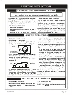
Lighting Instructions
Connecting the gas supply
After connecting the gas supply to the gas control on the
heater, the connections must be checked thoroughly for
leaks.
Remove the small piece of wood from the rear of the heater
and discard. Four small adhesive foam pads are included with
the unit and can be found in the accessory bag.
Hang the heater on the arms on the wall support bracket, taking
extreme care to ensure that the small diameter vent pipe fits
inside the smaller opening in the rear of the unit. (See Figure
9). The larger diameter vent pipe must then slide over the
outside flange opening.
Secure the unit to the
wall support bracket with the two screws provided.
Attach the
to the back of the unit so that
they may be read when necessary. These instructions are for
current and future use. Make sure they remain accesible after
the unit is installed.
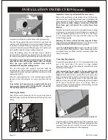
Connect the gas supply to the 3/8” (9.5 mm) pipe on the lower
part of the right side of the heater by using standard
connectors. Please refer to the cautionary remarks noted in the
beginning of this manual.
With the shut-off valve turned ON, but the gas control
knob on the heater OFF, apply liberal amounts of a soapy water
solution to all of the piping joints. A gas leak will cause
bubbles to form. Note any leaks in the piping system, then shut
off the gas at the shut-off valve, or at the gas meter or
propane/LP tank serving the building. Fix the leaking joint and
re-test the joints as directed above.
Once the supply is checked and does not leak, place the cover
on the unit. See Figure 10. Be sure the foam packing has been
removed. Secure the cover with the two nuts at the bottom of
the unit which you had removed when unpacking.
eventual water filtration or the entrance of bugs is necessary.
Press the flange against the outer wall surface and fasten the
vent cap to the wall using the 4 screws (provided with the unit)
in the holes prepared in the vent cap plate. Once the vent is
secured to the wall, proceed filling the gaps between the vent
plate and the wall with silicone sealing compound.
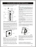
Inside the building, place the wall support plate (which is
taped inside the cabinet during shipment) over the open end of
the vent pipe and push the plate firmly against the interior wall.
Now level the plate with carpenter level and mark the
mounting holes with a pencil (see Figure 8). Remove the wall
support plate from the vent pipe and drill the two holes with the
appropriate drill bit.
Place the wall support plate over the vent pipe again and affix
the plate to the wall using the two screws provided with the
unit.
You might need to handle the introduction of the larger
pipe into the hole of the support plate with your fingers
since the pipe could have suffered some minor
deformation through the cutting process.
Note: hollow wall fasteners (also supplied with the unit)
are necessary for model MV 120. Models MV 130 and MV
145 can be mounted on the wall studs.
Mounting the furnace
Take off the cover by loosening the two screws at the bottom.
Pull the bottom away from the heater and lift it up off the tabs
on top.
INSTALLATION INSTRUCTIONS (cont.)
Figure 8
Figure 9
Figure 10
Page 10
MV1XX-1-0603
Содержание MV 120
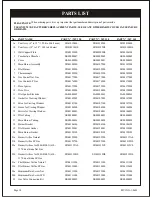
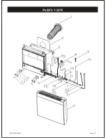
Страница 15: ...Page 15 PARTS VIEW MV1XX 1 0603 ...


