3
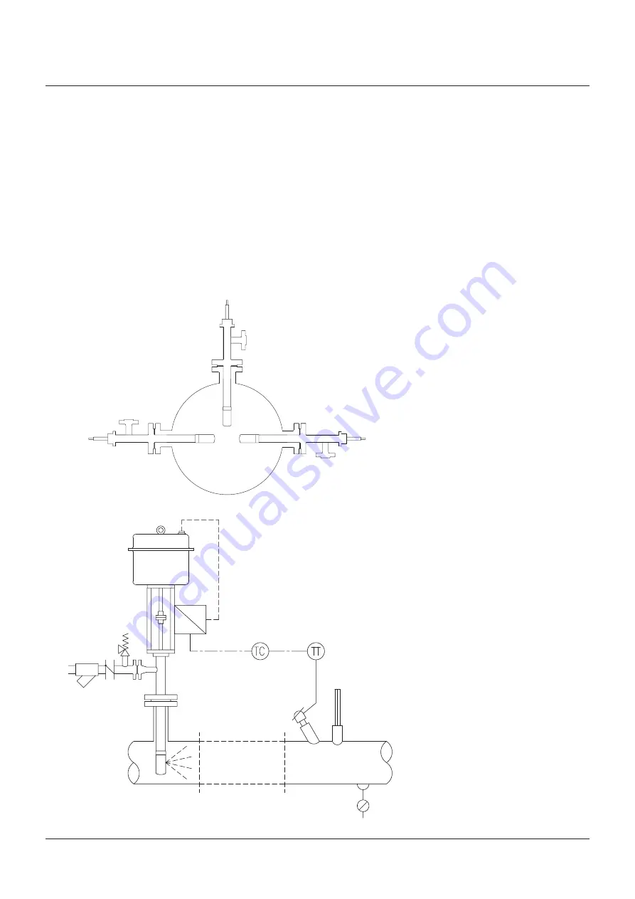
Figure 6
safety valve
Check valve
strainer
YarwaY
A.T.-Temp CryogeniC desuperheATer sTAndArd duTy
InstallatIon and MaIntenance InstructIons
The liquid supply should be of a good quality;
clean and filtered, and should have a constant
pressure as specified in the order documents.
each liquid supply line should be protected with
its own individual strainer with a maximum
element perforation size of 0.1 mm (0.4 mm
acceptable for nozzles ‘e’ size and up).
Where there are positive shut-off components
in the liquid supply (including electric actuators)
then a safety relief valve of an approved type
should be fitted. As in the case of the process
pipework, use gasketing and bolting in
accordance with the relevant piping code. Flush
out the liquid line before connecting to the
A.T.-Temp Cryogenic desuperheater mounting
flange (see Figure 6).
Figure 5
yarway supplies the A.T.-Temp Cryogenic
desuperheater as follows:
identification number:
xx. 37. xxxxx - Fabricated type with
non-balanced stem.
xx. 47. xxxxx - Fabricated type with
semi-balanced stem and
oversized trim all with the spray
cylinder tack welded to the body
extension pipe.
note:
horizontal orientated A.T.-Temp
Cryogenic desuperheater has to be installed
with a support for weight compensation.
pipe bends should always be of the long radius
type to assist in keeping the liquid droplets in
suspension, until complete evaporation has
taken place. installation may be in vertical or
horizontal piping, but the direction of liquid
injection should always be with the process
gas flow.
The A.T.-Temp Cryogenic desuperheater may
be mounted at 90° to the process pipe, for
all flow orientations, but avoid installation in
the vertically downwards position, wherever
possible (see Figure 5).


