


2 – 3
Section 2 • Operational Descriptions
Blower Package PLC Operation Manual •Vilter/Emerson • 35391BLP
• Deadband – Range above and below target pressure
where no speed adjustment will be made.
• Proportional Gain (Kp) – Proportional Term of the PID
equation
• Integral Gain (Ki) – Integral term of the PID equation
• Derivative Gain (Kd) – Derivative Gain of the PID
equation.
OPERATING MODES
The speed control of the blower package can be con
fi
g-
ured to operate in several ways, depending on the needs
of the site. This mode selection is made at the “Start
Menu” screen. There are four basic modes, described
below:
• Local-Auto: The blower controller will adjust the
speed of the blowers to maintain the target pressure
set point. The target pressure setpoint is set on the
local HMI. Blowers will run off of the PID controller’s
speed command or
fi
xed speed set point, according
to how the individual blowers are con
fi
gured.
• Local-Manual: The operator is in control of the indi-
vidual blower speeds from the local HMI. When in
Local-Manual mode, the operator controls the speed
of each blower by adjusting the manual speed set
points on the blower overview screen.
• Remote-Auto: The blower controller will adjust the
speed of the blowers to maintain the target pressure
set point. Blowers will run off of the PID controller’s
speed command or
fi
xed speed set point, according
to how the individual blowers are con
fi
gured. The tar-
get pressure setpoint is de
fi
ned by the DCS/Central
Controller via communications. (NOTE: Control by
Communications must be enabled to use this mode.)
• Remote-Manual: Individual blower speed commands
are controlled by a DCS or Central Controller via com-
munications. (NOTE: Control by Communications
must be enabled to use this method.)
In any of the above modes, all local alarms and trips will
still apply.
For safety reasons, remote mode is only enabled if
Control by Communications is enabled.
In the event that the communications link between the
blower PLC and the central controller/DCS is lost, the ac-
tion taken is selectable from the Con
fi
guration screen.
The machine will Trip or revert to Local mode and con-
tinue to run depending on the selection.
The blower PLC can be remotely commanded to Local or
Remote Mode if Control by Communications is enabled.
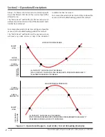
LOAD LIMITS AND FORCED UNLOADING
Reference example, Figure 2-1
To protect the blower package and process, the control-
ler will inhibit the blower from increasing speed or force
it to decrease speed if certain variables get outside of set
ranges. Load limits and forced unloading will also affect
blowers that are con
fi
gured to PID speed control. The
load limiting variable depends on what control mode the
blower package is in.
• In Discharge Pressure Control, the load limiting will
be controlled by suction pressure.
• In Suction Pressure Control, the load limiting will be
controlled by discharge pressure.
Three set points are used to control load limits and
forced unloading:
• Inhibit Loading: when this setpoint is reached, the
blower will not be allowed to increase speed
• Unload at: when this setpoint is reached, the blower
motor will decrease speed by a settable rate (forced
unload) until the “Unload To” setpoint is reached.
• Unload To: this is the setpoint at which the blower
motor will stop decreasing speed from a forced un-
load condition.
When a load limit or forced unload condition is active it
will be annunciated in the status banner on the overview
and menu HMI screens, and will also be logged in the
event list.
SAFETIES
The blower controller continuously monitors opera-
tional and process data and annunciates an alarm and/or
stops the machine if any condition becomes abnormal.
Two levels of safeties exist when an abnormal condition
is detected.
• Alarm: If active, alarms are annunciated on the blow-
er HMI. When activated, a popup screen showing the
date and time of the alarm and alarm message will
appear. Alarms are also logged in the Event List. An
alarm serves only as a warning to the operator; if an
alarm is active the machine is still allowed to run.
• Trip: If active, trips will shut the machine down or not
allow the blower to start. Trips are annunciated on
the blower HMI. When activated, a popup screen
showing the date and time of the trip and trip mes-
sage will appear. Trips are also logged in the Event
List.
Alarms and Trips may be general or blower-speci
fi
c. A
general trip will shut down the entire blower package,
a blower-speci
fi
c trip will only shut down the affected
Содержание Vilter PLC
Страница 1: ...Blower Package PLC Operation manual ...
Страница 2: ......
Страница 10: ...Blank TOC Blower Package PLC Operation Manual Vilter Emerson 35391BLP ...
Страница 18: ...1 8 Blank Blower Package PLC Operation Manual Vilter Emerson 35391BLP ...
Страница 30: ...3 2 Blank Blower Package PLC Operation Manual Vilter Emerson 35391BLP ...
Страница 34: ...4 4 Blank Blower Package PLC Operation Manual Vilter Emerson 35391BLP ...
Страница 42: ...5 8 Blank Blower Package PLC Operation Manual Vilter Emerson 35391BLP ...
Страница 48: ...6 6 Blank Blower Package PLC Operation Manual Vilter Emerson 35391BLP ...
Страница 54: ...7 6 Blank Blower Package PLC Operation Manual Vilter Emerson 35391BLP ...
Страница 62: ...9 6 Blank Blower Package PLC Operation Manual Vilter Emerson 35391BLP ...
Страница 68: ...10 6 Blank Blower Package PLC Operation Manual Vilter Emerson 35391BLP ...
Страница 117: ......


