3
General
Installation to Operate the
Ceiling Fan, Downlight
and Uplight
Your Emerson Ceiling Fan/Light Control
consists of either a hand-held transmitter
with wall caddy and/or a wall control as
well as a receiver which is mounted under
the fan ceiling cover. The wall control and
remote control are designed to control
your ceiling fan speed, airflow direction,
and light intensity.
IMPORTANT
It is important that you also follow the
instructions found in the Owner's
Manual supplied with your Ceiling Fan.
Pay particular attention to the Safety
Instructions and WARNING notes.
NOTE 1: On the CF4600 Series Ceiling
Fan, install the fan blades and switch
cup assembly in accordance with the
instructions in the ceiling fan owner’s
manual, then proceed with steps 1
through 10 below.
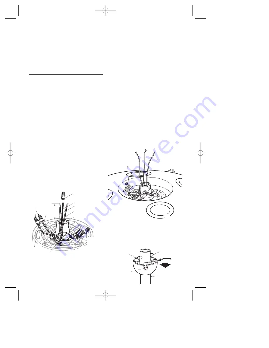
1. Remove the wire connectors from the
red and brown wires. Cut the white,
blue and black wires about 3" above
the motor coupling (Figure 1). Strip
insulation 1/2" from end of white, blue,
red and brown wires. Install a wire
connector on the black wire; this wire
will not be used.
YELLOW WIRE FROM MOTOR
COUPLING (See NOTE 3)
BROWN
WIRE
RED WIRE
YELLOW WIRE
FROM UPLIGHT
(See NOTE 3)
REMOVE WIRE
CONNECTORS
FROM RED AND
BROWN WIRES
(See NOTE 1)
3"
BLUE WIRE
BLACK WIRE
WHITE WIRE
CAP BLACK WIRE
USING A WIRE
CONNECTOR
REMOVE
WIRE
CONNECTOR
MOTOR COUPLING
Figure 1
NOTE 2: On Model CF1, CF2400, and
CF2800 Series Ceiling Fans, the red
and brown wires from the motor are
connected to red and brown wires from
the reversing switch. Remove the wire
connectors and separate these wires.
Using wire connectors, cap the red and
brown wires from the reversing switch;
these wires will not be used.
NOTE 3: If your ceiling fan does not
have a built-in uplight, these yellow
wires will not be present.
2. Remove the wire connector (Figure 1)
from the yellow wires (See NOTE 3).
Separate the yellow wires, and cap the
yellow wire coming from the motor
coupling.
NOTE 4: On early Model CF2400 Series
Ceiling Fans, cut the orange wire
midway between the motor coupling
and the housing (Figure 2). Cap the
orange wire from the motor coupling
using a wire connector. The orange
wire from the housing will get
connected to the uplight yellow wire in
Step 6.
3. Loosen the setscrew in the hanger ball,
slide the ball down the hanger pipe,
and remove the clevis pin. Then slide
the hanger ball off the hanger pipe
(Figure 3). Retain all parts.
DOWNROD
CLEVIS PIN
SETSCREW
HANGER
BALL
Figure 3
ORANGE WIRE
(See NOTE 3)
Figure 2
BP7253-2 4/28/06 11:58 AM Page 3


