Safety
Information
Introduction
Product
information
System
design
Mechanical
installation
Electrical
installation
Getting
started
Optimisation
Parameters
Technical
data
Component
sizing
Diagnostics
Unidrive SP Regen Installation Guide
205
Issue Number: 2 www.controltechniques.com
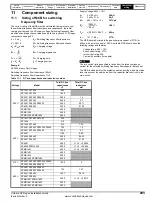
Example: Charging time
Total softstart resistance of 24
Ω
(2 x 48
Ω)
in parallel, and a total DC bus
capacitance of 11600
µ
F
T
constant
= Resistance
softstart
x Total Capacitance
DC bus
24 x (11600 x10
-6
) = 0.278
T
constant
x 5 = T
charge
0.2784 x 5 = 1.39s
Selection
From the above calculations for a peak charging current of 31.108A with
a charge time of 1.392s a magnetic overload with the following
characteristics could be used:
2A nominal rating (31.108/20 = 1.5554 rounded to 2A)
O/L = 15.5 (2 x 15.5 = 31)
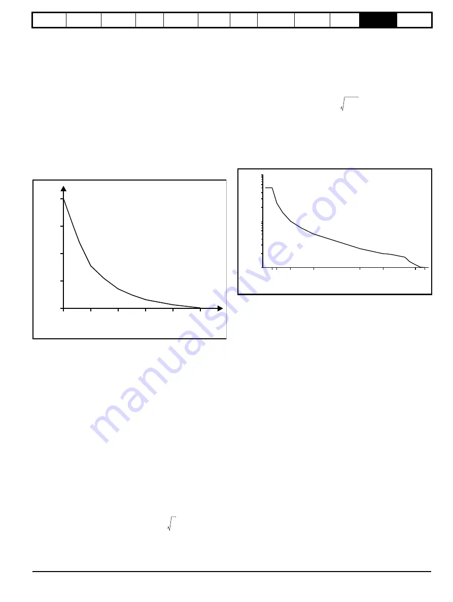
Plotting the exponential charging current for the soft start circuit against
the trip characteristic curve for the overload will also ensure no spurious
tripping during charging time.
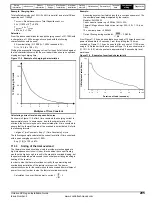
Figure 11-2 Example of charging characteristics
Calculating current level on exponential curve
As shown in Figure 11-2, after 5 time constants the charging current is
approximately zero. In some cases, due to the characteristic of the
overload, the current may have to be calculated after 4 time constants to
ensure that the thermal trip area of the overload is not activated. Refer to
the following formula:
I at given Time Constant = Exp [-1 (Time Constants)] x I
peak
The following example calculates the current level after 3 time constants
with a peak charging current of 100A:
Exp [-1 (3)] x 100 = 4.97A
11.3.3 Sizing of thermal overload
The thermal overload should be sized to provide protection against a
high impedance short circuit. Under this condition the current flowing
would not be high enough to result in the magnetic overload tripping, but
the power dissipated would exceed the nominal power rating resulting in
heating of the resistor.
In order to size the thermal overload correctly, the power rating and
overload characteristics of the resistor are required. The power
characteristic curve for the resistor should be converted from multiples of
power to current in order to size the thermal overload correctly.
Calculation to convert from power to current:
Example:
Assuming a system fault which results in a continuous power of 10 x
the nominal power being dissipated by the resistor.
Resistor, 24
Ω
296W
Peak current at power up = 528Vac / 24
Ω
= 22A
Thermal / Magnetic overload current rating = 22A / 20 = 1.1A (use
1.6A)
10 x nominal power = 2.960kW
Current flowing during overload =
From Figure 11-3 it can be seen that an overload of 10 times the nominal
power is allowable for 5 seconds. From this plotting the 10 times
overload on Figure 11-1 it can be seen that for a current of 11.10A when
using a 1.6A breaker that the overload will trip at 7 x the nominal current
(11.10/1.6 = 6.9), which equates to approximately 5 seconds trip level
worst case.
Figure 11-3 Example of overload characteristic
25
50
75
100
0
0
1
2
3
4
5
Multiples of Time Constant
%
C
ha
rg
in
g
C
urre
nt
P
R
----
I
=
2960
24
-------------
11.01A
=
10
1
0 1 2
5
10
Duration of Load (seconds)
%
Mu
ltipl
es
o
f ra
te
d
Po
we
r
100
20
25
50 100
Содержание SP1201
Страница 219: ......
Страница 220: ...0471 0029 02 ...

