Installation, Operation and Maintenance Manual
VA-DC-000-1952 Rev. 0
April 2021
Shafer ECAT
Emission Controlled Actuator Technologies
Страница 1: ...Installation Operation and Maintenance Manual VA DC 000 1952 Rev 0 April 2021 Shafer ECAT Emission Controlled Actuator Technologies ...
Страница 2: ...Installation Operation and Maintenance Manual VA DC 000 1952 Rev 0 This page intentionally left blank Notes April 2021 ...
Страница 3: ...the Stroke Limit Stops 9 2 7 Hydraulic Fluid 10 2 8 Accumulator 10 Section 3 Electrical Connections 3 1 Main Electrical Connections 13 3 2 Sealing Cable Conduit Entries 13 Section 4 Set up Start up Procedure 4 1 Preparation 14 4 2 Initial Check of the Unit 15 4 3 Initial Connections 15 4 4 Initial Pre Charge 15 4 5 Initial Reservoir Fill 15 4 6 Hydrostatic Pressure Function Test 15 4 7 Final Start...
Страница 4: ...r actuator movement will cause the thermal volume controller rod to move down This movement operates the motor control switch to the Motor On position automatically starting the electric driven hydraulic pump The pump will run until the hydraulic fluid in the power header line and all accumulators has been replenished When the header and accumulator have been filled the thermal volume controller r...
Страница 5: ...ator s piston The hydraulic fluid stored in the Accumulator 76 originates from the Oil Reservoir 60 Fluid is drawn from the Oil Reservoir 60 and through the suction line by a Hydraulic Pump 67 The hydraulic pump 67 forces the fluid through the discharge line and into the Accumulator 76 The ECAT system has one electric motor driven Hydraulic Pump 67 The pump is controlled by a motor control switch ...
Страница 6: ...more specific and significant information regarding the actuator than this general manual It is the responsibility of the user to ensure proper safety practices are utilized Always take necessary precautions and use proper protective equipment when dealing with compressed gasses compressed hydraulic fluid pinch points and electricity Safety notices are presented in this manual in three forms Warni...
Страница 7: ...efinitions Abbreviation Definition IOM Installation Operation Manual ESD Emergency Shutdown FS Fail safe DA Double Acting MAWP Maximum Allowable Working Pressure MOP Maximum Operating Pressure MCC Motor Control Center LS Limit Switch PS Pressure Switch NC Normally Closed NO Normally Open CCW Counterclockwise CW Clockwise OL Overload PPE Personal Protective Equipment GA General Arrangement Drawing ...
Страница 8: ...mersed in water or buried in snow Check for any unpainted or exposed metal surfaces and make sure they are protected with a coating of grease to prevent any corrosion Cover the system to prevent damage from site debris 2 1 2 Tools and Materials Required To complete these procedures you will need the following documentation for the ECAT Actuator and items indicated in the table below General Arrang...
Страница 9: ...the run of the valve 2 2 4 The ECAT Actuator may be mounted to the valve at any time regardless of whether the valve is under pressure 2 3 Actuator Preparation 2 3 1 Once the ECAT Actuator is uncrated and cleaned for installation check to ensure there will be no interference with piping or other structure when the actuator is properly mounted to the valve 2 3 2 Check that all mounting materials su...
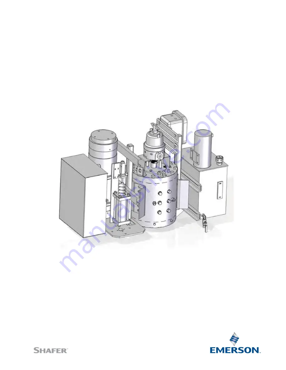
Страница 10: ...rol enclosures Straps and chains can become entangled and cause damage to these components NOTE Do not use hydraulic tubing and electrical cable for lifting CAUTION Be sure to use appropriately rated crane hoist and straps chains to raise and lower the actuator 2 4 1 Shafer Rotary Vane Actuator Lifting Use the integrated lifting eyes only to lift and move the ECAT system Figure 1 ECAT System Mount...
Страница 11: ... Rev 0 April 2021 8 Section 2 Installation Installation Figure 2 ECAT System Mounted on the Shafer Rotary Vane Actuator CAUTION Never lift the actuator with a valve attached Always handle actuator valve assemblies by attaching lifting equipment to the valve only ...
Страница 12: ...n and free of debris to permit proper fit up 2 5 5 Prior to mounting grease the coupling bore and the bore of the actuator NOTE Do not apply grease to the mounting flange surfaces on the valve or the adaptor 2 5 6 Install the stem key and grease it keys may be held in place with tape 2 5 7 Install the coupling onto the stem and stem key 2 5 8 Install the coupling key and grease it 2 5 9 Carefully ...
Страница 13: ...10 Excel 22 Low Temperature Fluid use with 50 F to 140 F 46 C to 60 C applications Mobil Univis HVI 13 Although other brands of fluid matching the same specifications may be used to maintain the warranty and ensure trouble free operation always check with the factory before substituting any other fluid 2 8 Accumulator 2 8 1 Introduction The ECAT Actuator is equipped with a hydraulic accumulator As...
Страница 14: ... Valve 74 and Thermal Volume Controller Hydraulic Isolation Valve 75 d Connect the pipeline gas to isolation valves 90 and 91 e Ensure the Pneumatic Blow Down Valve 87 is closed f Ensure Pneumatic Isolation Valve Lockable 83 is open g Slowly open isolation valves 90 and 91 h Slowly open Pneumatic Blow Down Valve 87 to purge the pneumatic side of the control of air Close valve 87 NOTE The pneumatic...
Страница 15: ...k detector from Swagelok or comparable If any leaks are detected close isolation valves 90 and 91 and open Pneumatic Blow Down Valve 87 to vent all pressure from the circuit Repair any leaks present and repeat steps from Section 2 8 2 WARNING This unit contains high pressure hydraulic fluid and pipeline gas Exercise caution when performing any type of maintenance Wear proper safety attire and requ...
Страница 16: ...ram for the electrical connections to the MCC 3 2 Sealing Cable Conduit Entries Seal the cable and conduit entries in accordance with the National Electric Code or your country standard and applicable local codes All conduit entries should be sealed against the site environment All unused conduit entries must be sealed with threaded metal plugs WARNING Always verify electrical power is disconnecte...
Страница 17: ... 4 1 Preparation 4 1 1 Safety First WARNING Hydraulic Pressure Ensure that test personnel and witnesses are properly informed of the hazards involved with high pressures and the proper safety barriers are employed Never check for leakage using your fingers or hands Fluid under high pressure can inject into the skin and cause severe damage or death Always use an implement such as a piece of paper o...
Страница 18: ...If power is not connected follow the instructions under Section 3 Electrical Connections before continuing CAUTION Before the actuator is stroked ensure the reservoir has been filled with fluid to the proper level See Section 2 7 Hydraulic Fluid 4 4 Initial Pre Charge Refer to Section 2 8 Accumulator for the pre charge setup of the ECAT 4 5 Initial Reservoir Fill Ensure the ECAT Oil Reservoir 60 i...
Страница 19: ...and fluid will start to fill the Accumulator 4 6 11 Observe the Level Viewer 62 to ensure enough fluid is present to fill the Accumulator 76 In the event the fluid level drops to the trip point of the Level Switch 63 the Electric Motor 69 will stop Add fluid to the Reservoir 60 if needed 4 6 12 Allow the Pump to run filling the Accumulator until the Thermal Volume Controller moves and trips the Mo...
Страница 20: ...ines up to Power Oil Isolation Valve 73 should be filled and purged of all air per Section 4 6 Under normal operating conditions the Hand Off Auto selector switch will be set to Auto Refer to the Actuator and Control IOM for specific steps in operating the actuator and control in conjunction with the ECAT hydraulic system 4 8 Optional Instrumentation The ECAT system can be supplied with a Hydrauli...
Страница 21: ...the correct terminals 3 Circuit breaker is tripped off ECAT is ON but motor does not run 1 Ensure the Hand Off Auto switch is in the proper position 2 Ensure the customer field power wiring is an adequate size 3 Power supply is insufficient 4 Check to see if thermal overload is tripped 5 Ensure the Motor Start Stop Switch 78 is set properly ECAT motor runs but fails to develop sufficient pressure ...
Страница 22: ...enerally unnecessary Normally recommended service interval for Shafer Bettis actuators is five years or maximum actuator seal life cycle whichever occurs first NOTE Storage time is considered as part of the Service Interval time It is recommended that Service Kits be ordered approximately three 3 months prior to scheduled maintenance to assure availability Observe the function of the Accumulator 7...
Страница 23: ... with a leak detection product such as Snoop liquid leak detector from Swagelok or comparable Check handpump operation functions properly If When possible perform a function test See Section 4 6 for instructions on how to perform a function test Check accumulator and thermal volume controller function Check the breather on the hydraulic reservoir Check the return filter if included Qualified servi...
Страница 24: ...uest We reserve the right to modify or improve the designs or specifications of such products at any time without notice For complete list of sales and manufacturing sites please visit www emerson com actuationtechnologieslocations or contact us at info actuationtechnologies emerson com NORTH SOUTH AMERICA 19200 Northwest Freeway Houston TX 77065 USA T 1 281 477 4100 Av Hollingsworth 325 Iporanga ...