56
MODEL 5081-A
SECTION 10.0
CALIBRATION - FREE CHLORINE
10.2 PROCEDURE — zEROING THE SENSOR
1. Place the sensor in the zero standard (see Section 10.1). Be sure no air bubbles are trapped against the mem-
brane. The sensor current will drop rapidly at first and then gradually reach a stable zero value. To monitor the
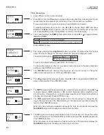
sensor current, go to the main display. Press DIAG followed by NEXT. The
SEnSor Cur
prompt appears. Press
ENTER to view the sensor current. Note the units: nA is nanoamps; µA is microamps. Typical zero current for
a free chlorine sensor is -10 to +10 nanoamps.
A new sensor or a sensor in which the electrolyte solution has been replace may require several hours (occa-
sionally as long as overnight) to reach a minimum zero current. DO NOT START THE ZERO ROUTINE UNTIL
THE SENSOR HAS BEEN IN ZERO SOLUTION FOR AT LEAST TWO HOURS.
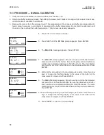
2. Press CAL on the remote controller.
3. The
SEnSor O
prompt appears. Press ENTER.
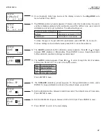
4. The screen shows the value (in units ppm) below which the reading
must be before the zero current will be accepted. The screen shows
0.02
. Therefore, the reading must be below 0.02 ppm before the zero
will be accepted. For a typical 499ACL-01 sensor, 0.02 ppm corre-
sponds to about 7 nA. To change the zero limit value, see Section 7.8.3.
Press ENTER.
NOTE
The number shown in the main display may change. During the
zero step, the previous zero current is suppressed, and the con-
centration shown in the main display is calculated assuming the
residual current is zero. Once the transmitter accepts the new zero
current, it is used in all subsequent measurements.
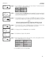
5. The
tiME dELAy
message appears and remains until the zero current
is below the concentration limit shown in the previous screen. If the cur-
rent is already below the limit,
tiME dELAy
will not appear. To bypass
the time delay, press ENTER.
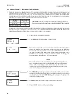
6.
O donE
shows that the zero step is complete. Press EXIT.
7. Press RESET to return to the main display.
CALIBRATE
0 dOne
EXIT
CALIBRATE
Sensor 0
EXIT
NEXT ENTER
CALIBRATE
time delay
EXIT
ENTER
CALIBRATE
0 at 0
.02
EXIT
ENTER
Содержание Rosemount Analytical HART 5081-A-HT
Страница 22: ...FIGURE 4 2 FM Intrinsically Safe Installation Label 16 ...
Страница 25: ...FIGURE 4 4 CSA Intrinsically Safe Installation Label 19 ...
Страница 26: ...FIGURE 4 5 CSA Intrinsically Safe Installation 1 of 2 20 ...
Страница 27: ...FIGURE 4 5 CSA Intrinsically Safe Installation 2 of 2 21 ...
Страница 108: ...FIGURE 4 Wiring to Model 5081 102 MODEL 4000 WIRING ...
Страница 110: ...104 ...


