14
Reference Manual
00809-0100-4825, Rev CB
Section 2: Installation
March 2014
Installation
2.4
Multichannel installations
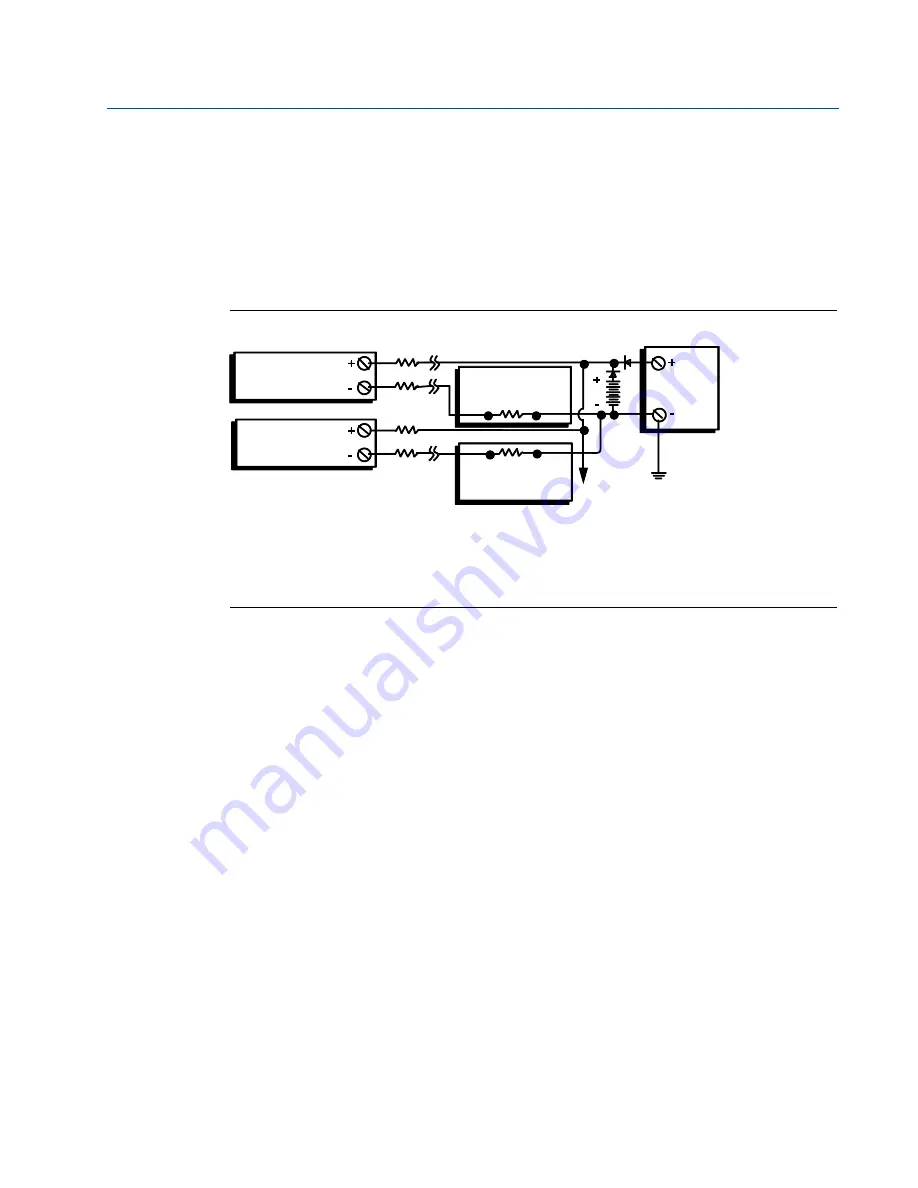
Several transmitters can be connected to a single master power supply, as shown in
.
In this case, the system may be grounded only at the negative power supply terminal. In
multichannel installations, where several transmitters are dependent on one power supply and
the loss of all transmitters would cause operational problems, consider an uninterrupted power
supply or a back-up battery. The diodes shown in
discharging of the back-up battery.
Figure 2-5. Multichannel Installations
2.5
Set the switches
2.5.1
Failure mode
Each transmitter continuously monitors its performance during normal operation with an
automatic diagnostic routine of continuous timed series of checks. If an input sensor failure or a
transmitter electronics failure is detected, the transmitter outputs the low or high alarm,
depending on the failure mode configuration.
For sensor temperature outside of range limits:
Standard Saturation Levels:
3.90 mA on the low end
20.5 mA on the high end
NAMUR-Compliant Saturation Levels:
3.80 mA on the low end
20.5 mA on the high end
These values are also custom configurable by the factory or using the Field Communicator or
AMS. See
“Alarm and saturation” on page 36
for instructions on how to change the alarm and
saturation levels with the Field Communicator.
A. Transmitter no. 1
E. Readout or Controller no. 2
B. Transmitter no. 2
F. Backup battery
C. R
Lead
G. dc Power supply
D. Readout or Controller no. 1
H. To additional transmitters
A
B
C
C
C
D
E
H
G
F
Between 250
and 1100
if no load resistor.


