6
PENBERTHY
SERIES U FLAT GLASS GAGES
INSTALLATION, OPERATION AND MAINTENANCE INSTRUCTIONS
8 REMOVAL - DISASSEMBLY - REASSEMBLY
WARNING
Use only qualified, experienced personnel who
are familiar with liquid level gage equipment and
thoroughly understand the implications of the
tables and all the instructions. DO NOT proceed
with any maintenance unless the liquid level gage
has been relieved of all pressure or vacuum, has
been allowed to reach ambient temperature and
has been drained or purged of all fluids. Failure
to follow instructions can cause serious personal
injury and property damage.
8.1 Disassembly
Secure a workbench longer than the liquid level
gage, and sufficiently wide to lay out parts as
they are removed.
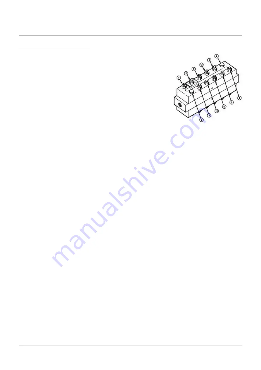
1. Hold gage firmly; loosen cap screws and
nuts starting at both ends of each section
and then proceed from both ends to the
center of each section as shown in Figure 2.
Note:
if maintenance is to be performed on
one (1) side of the gage only, the cap screws
on the opposite side of the gage do not need
to be removed. If these screws are removed,
then all glass, gaskets and cushions on
both sides of the gage must be destroyed,
disposed of and replaced.
2. Nut loosening sequence
- Remove nuts, cap screws, washer and
nameplate.
- Tap covers with rubber hammer as needed
to loosen and remove.
- Remove cushions, glass and gaskets.
- Tap liquid chamber or remaining covers as
necessary with rubber hammer to break
loose and remove remaining components.
- Remove, destroy and dispose of all
glass, cushions and gaskets. Under no
circumstances should these components
be re-used or installed on a gage.
Note:
if size of gage is smaller than shown,
follow spiraling sequence from the ends
until all bolting is loosened.
WARNING
Once used, cushions and gaskets are deformed
permanently by compression and, if re-used,
may cause leaks and high stress points resulting
in glass breakage. Glass may contain hidden
damage and internal stresses caused by previous
usage. If re-used, the glass may break under
pressure causing severe personal injury or
property damage.
FIGURE 2
Nut loosening sequence
8.2 Inspection of glass seating surfaces
Clean the glass seating surfaces on the liquid
chamber and cover with a soft metal scraper
(preferably brass) to remove all burrs, rust and
remnants of the previous gaskets and cushions.
Exercise extreme care to avoid gouging or
scarring gasket and cushion seating surfaces.
Use a known flat piece of metal the same
approximate length as the glass or a new
piece of glass and a thickness gage to check
flatness of each glass seating surface on liquid
chamber and under cover. Surfaces on the
liquid chamber must be flat within 0.001 inch
(0.03 mm) and on the cover must be flat within
0.002 inch (0.05 mm). If any one surface is
found to be beyond the tolerances described
above, the entire gage must be disposed of and
replaced.
WARNING
Flatness of glass seating surfaces outside the
tolerances specified above is an indication of the
gage having been overstressed through repeated
exposure to mechanical, thermal or hydraulic
shock during its previous service. Operation of a
liquid level gage which has been overstressed will
result in abnormal stresses on the glass which
may cause glass to break with resulting sudden
release of pressure, leakage of contained fluid,
serious personal injury or property damage.
Glass seating surfaces should NOT be
machined to achieve seating tolerance. The
chamber and cover are designed for a critical
thickness to achieve the pressure/temperature
ratings. Machining glass seating surfaces may
result in non-compliance to the necessary
critical thickness due to material removal.


