


3
PENBERTHY
MODEL CTE MIXER / HEATER
INSTALLATION, OPERATION AND MAINTENANCE INSTRUCTIONS
4 INSTALLATION
Installation should only be undertaken by
qualified, experienced personnel who are
familiar with this equipment and have read and
understand all the instructions in this manual.
The user should refer to the relevant technical
data sheet or product proposal to obtain
dimensional information for the specific size
and model of CTE.
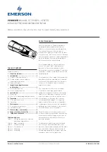
Check the cut-away view (Figure 1) for the
location of the threaded inlet.
4.1 Mounting
A CTE can be mounted in any position. The
supply line and manifold piping to multiple
CTEs must be sized to supply uniform pressure
to each CTE.
It is important that the CTE be positioned
within the tank so as to insure the free flow of
liquid to be mixed or heated into and out of the
unit(s). The greatest agitation occurs within the
discharge plume; therefore, the discharge end
should be aimed towards the most remote part
of the tank. On the other hand, the intake end
of the unit must be far enough from the tank
corner or wall to allow the free flow of liquid
into the suction openings.
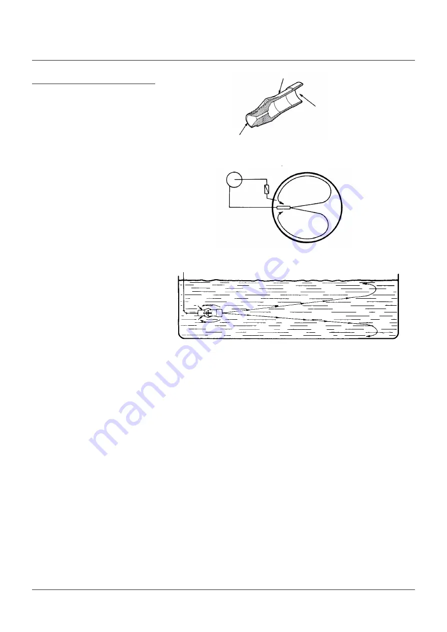
Tank shape and size influence the placement
and number of CTEs required to maintain even
agitation or temperature distribution. With a
spherical tank, a single CTE mounted as shown
in Figure 2 makes the best use of the mixing
and heating characteristics of the CTE. With
no corners to impede liquid flow, the liquid
circulates evenly and undisturbed.
In a cylindrical, square or rectangular tank, the
angular intersection of surfaces can interrupt
liquid flow patterns and cause liquid stagnation
in these areas. A single CTE mounted as shown
in Figure 3 will minimize this. Whenever the
ratio of length to diameter of the tank is greater
than 2:1 (such as tank trucks or railroad cars),
it is recommended that multiple CTEs be used.
FIGURE 1
FIGURE 2
Discharge
Inlet
Spherical
Body
4.2 Effect of related piping and precautions
1. For mixing
a. Operating liquid supply line pressure loss
must be taken into account when applying
CTEs.
b. Supply line must be clean and should be
provided with a strainer to prevent foreign
materials from clogging the mixer.
c. CTEs must be fully submerged to prevent
liquid from splashing and drawing
atmospheric air, and to promote maximum
mixing.
d. Clearance should be provided for removal of
the CTE.
e. Provisions should be made for a pressure
gauge connection at or near the CTE
inlet. It may become necessary to install a
pressure gauge if operating difficulties are
encountered.
f. Inlet piping must be secured to the tank wall
near the CTE to keep strain off piping when
in operation.
g. Supply line and manifold piping must be
sized to supply adequate pressure equally to
each CTE when multiple CTEs are used.
2. For heating
a. Steam must not have more than 20°F (-7°C)
of superheat or performance will differ from
that published in the relevant technical
data sheet or product proposal referred to
previously.
b. Steam line pressure loss must be taken into
account when applying CTEs.
c. The steam line must be clean and should be
provided with a strainer to prevent foreign
materials from clogging heater.
d. The steam line must be insulated and as
short as possible to prevent condensation
and friction losses.
e. CTEs must be fully submerged to prevent
liquid from splashing and to promote
condensation.
f. Clearance should be provided for removal of
the CTE.
g. Provisions should be made for a pressure
gauge connection at or near the CTE
inlet. It may become necessary to install a
pressure gauge if operating difficulties are
encountered.
h. Steam piping must be secured to the tank
wall near the CTE to keep strain off piping
when in operation.
i. The steam supply valve must be a quick
opening type installed as close to the CTE as
practical.
FIGURE 3


