NZ/NZ-M and NZOS/NZOS-M Series
17
Figure 7.
NZ Series Main Valve Assembly (continued)
VERSION WITH INDICATOR
INDICATOR DETAIL
VERSION WITH TRAVEL INDICATOR
Страница 1: ...NZ NZ Mand NZOS NZOS MSeries Pressure Reducing Regulators Instruction Manual D103764X012 January 2022 ...
Страница 2: ...odes rules and regulations and by strictly following instructions by Emerson Process Management Asia Pacific Pte Ltd Regulator Technologies Installation operation and maintenance procedures performed by non qualified personnel may result in an unsafe operation resulting in equipment damage or personal injury Use qualified personnel when installing operating and maintaining Types NZ NZ M and NZOS N...
Страница 3: ...se of failures these pilots with single diaphragm will cause a fail open reaction of the regulator Types JPLC and JPHC Double diaphragm pilot Type JPLC outlet pressure range of 0 5 to 30 bar 7 25 to 435 psig Type JPHC outlet pressure range of 28 to 65 bar 406 to 943 psig The Types JPLC and JPHC can be used as the pilot on single stage pressure reducing regulators as the monitor pilot in wide open ...
Страница 4: ...ed pressure is 10 bar Table 1 Main Valve Body Sizes End Connection Styles and Body Ratings MAIN VALVE BODY SIZE MAIN VALVE BODY MATERIAL END CONNECTION STYLE STRUCTURAL DESIGN TRATING DN NPS bar psig 25 1 WCB WCC or LCC Steel ANSI 150RF 20 290 ANSI 300RF 51 740 ANSI 600RF 1 102 1480 50 2 ANSI 150RF 20 290 ANSI 300RF 51 740 ANSI 600RF 1 102 1480 80 3 ANSI 150RF 20 290 ANSI 300RF 51 740 ANSI 600RF 1...
Страница 5: ...ation monitoring keeps the fluid gas in line Also testing is relatively easy and safe To perform a periodic test on a monitoring regulator increase the outlet set pressure of the working regulator and watch the outlet pressure to determine if the monitoring regulator takes over at the appropriate outlet pressure Wide Open Monitoring Systems There are two types of wide open monitoring systems upstr...
Страница 6: ...al Schematic TYPE JP PILOT TYPE NZ MAIN VALVE INLET PRESSURE OUTLET PRESSURE LOADING PRESSURE PILOT SUPPLY PRESSURE ATMOSPHERIC PRESSURE TYPE JP PILOT L LOADING B SENSING S SUPPLY INLET PRESSURE OUTLET PRESSURE LOADING PRESSURE PILOT SUPPLY PRESSURE ATMOSPHERIC PRESSURE TYPE JP PILOT L LOADING B SENSING S SUPPLY INLET PRESSURE OUTLET PRESSURE LOADING PRESSURE PILOT SUPPLY PRESSURE ATMOSPHERIC PRES...
Страница 7: ... manually reset before it can be put back in service To reset the power stage use the handle hanging outside the BM and rotate it clockwise slowly 4 Installation WARNING Personal injury or equipment damage due to bursting of pressure containing parts may result if this regulator is overpressured or is installed where service conditions could exceed the limits given in the Specification section and...
Страница 8: ...eam regulator to the upstream pipe Working Monitor Regulator 4 JP Series pilots have a 1 8 NPT vent connection in the spring case The pilot vent opening should be pointed down Protect the vent opening from condensation or clogging To remotely vent gas from the spring case connect piping or tubing to the spring case connection The piping or tubing should vent to a safe location have as few elbows a...
Страница 9: ...strictor is normally set at the tightest mode till it can no longer be screwed in the clockwise direction Observe extreme caution during unscrewing the restrictor so that it does not come out of the pilot body face In the event of hunting of the stable outlet pressure unscrew the restrictor slowly in increment of 1 4 turn until pressure stabilizes two turns at most Startup 1 Make sure all block va...
Страница 10: ... 4 for proper torque values To avoid personal injury or property damage from sudden release of pressure isolate the regulator from the pressure system and release all pressure from the pilot and main valve before performing maintenance operations Once the maintenance is carried out and regulator is assembled an external leakage test and lock up test must be carried out Eye nuts are installed to ai...
Страница 11: ...cage 13 Insert ring snap key 32 into the groove between body key 2 and sleeve guide key 5 Lightly lubricate O rings keys 22 and 33 and put them back 14 Slide sleeve key 3 and stem key 7 into sleeve guide key 5 then put spring key 6 back Make sure the blade and surface of sleeve key 3 won t be damaged or scratched 15 Place bonnet key 8 on top of body key 1 then insert bushing key 9 into the clearan...
Страница 12: ...for JPLO Series keys 50 51 52 53 57 63 108 for JPHO Series keys 50 51 52 57 63 108 Loose nut key 63 6 Types remote pressure loaded only Take out O ring key 113 for damage or wear and replace if necessary 7 Inspect the diaphragm key 51 for damage or wear and replace if necessary 8 Loose sleeve key 47 then take out O rings keys 66 and 67 disk key 39 and spring key 44 9 Inspect the rubber parts of di...
Страница 13: ...2 Remove restrict pin key 49 carefully 3 Inspect the small hole on restrict make sure it has not been blocked 4 Inspect O ring key 65 for damage or wear and replace if necessary Lightly lubricate O ring before placing it back 5 Insert restrict pin key 49 into main body and tighten 6 Install screw key 102 and washer key 103 8 Parts Ordering Each NZ NZ M or NZOS NZOS M Series regulator is assigned a...
Страница 14: ...127 Sensing Line 128 Sensing Line 129 Bolt 130 O Ring 131 O Ring 132 Sensing Line 133 Bushing 134 Stem 135 Connection 136 Bonnet Seat 137 Bonnet Key Description JP Series Pilots Figures 10 and 11 35 Upper Spring Seat 36 Spring 37 Support 38 Side Cover 39 Disk 40 Spring Cover 41 Orifice 42 Spring 43 Filter 44 Spring 45 Body 46 Plate 47 Sleeve 48 Rectangle Bar 49 Restrict Pin 50 Bar 51 Diaphragm 52 ...
Страница 15: ...en lubricated Table 5 JP Series Pilot Torque Specifications PART NUMBER JP SERIES PILOT TORQUE SPECIFICATIONS N m Sleeve key 47 Bolt key 60 Bolt key 61 Nut key 62 Nut key 63 Diameter M16 M10 M10 M6 M8 Torque 7 to 8 28 to 32 28 to 32 3 to 4 6 to 8 Note All torque values are for parts that have been lubricated Table 6 Failure Mode Analysis PART NAME CONDITION CAUSE EFFECT NZ NZ M SERIES REACTION MOD...
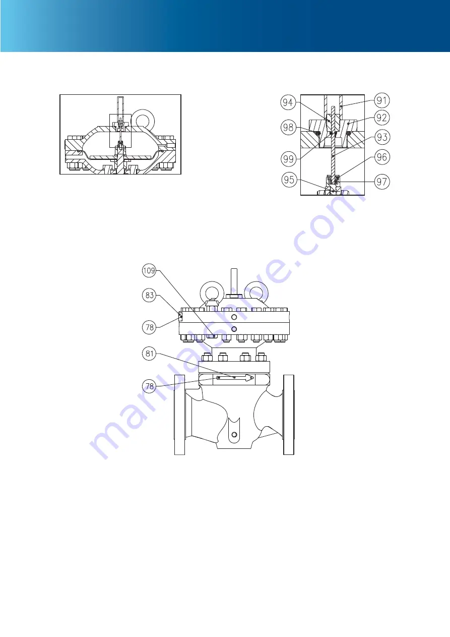
Страница 16: ...NZ M and NZOS NZOS M Series 1616 A Figure 7 NZ Series Main Valve Assembly TYPE NZ ALL SIZE ANSI 600 6 ANSI 300 O RING RETAINER DETAIL 1 ACTUATOR INSIDE DETAIL TYPE NZ M WIDE OPEN MONITORING VERSION VIEW A ...
Страница 17: ...NZ NZ M and NZOS NZOS M Series 17 Figure 7 NZ Series Main Valve Assembly continued VERSION WITH INDICATOR INDICATOR DETAIL VERSION WITH TRAVEL INDICATOR ...
Страница 18: ...NZ NZ M and NZOS NZOS M Series 1818 Figure 7 NZ Series Main Valve Assembly continued VERSION WITH TRANSDUCER DETAIL K VERSION WITH LINER TRANSDUCER ...
Страница 19: ...Z NZ M and NZOS NZOS M Series 19 Figure 8 NZ Series Pilot Mounting Assembly NZ WITH JPLO JPHO PILOT NZ WITH JPLC JPHC PILOT JPLO JPHO JPLC JPHC PILOT NZ MAIN VALVE DN 25 THROUGH 100 NPS 1 THROUGH 4 INLET ...
Страница 20: ...NZ NZ M and NZOS NZOS M Series 2020 Figure 8 NZ Series Pilot Mounting Assembly continued NZ WITH JPLC JPHC PILOT NZ WITH JPLO JPHO PILOT NZ MAIN VALVE JPLO JPHO JPLC JPHC PILOT INLET DN 150 NPS 6 ...
Страница 21: ...d NZOS NZOS M Series 21 Figure 9 NZ Series Working Monitor Mounting Assembly NZ WITH JPLCM JPLCW PILOT NZ WITH JPLCM JPLCW PILOT INLET SUPPLY P1 TO WORKING MONITOR NZ MAIN VALVE INLET WORKING PILOT MONITOR PILOT ...
Страница 22: ...SECOND STAGE DIAPHRAGM ASSEMBLY DETAIL FOR TYPE JPHO JPHOW JPHOM MONITOR PILOT SECOND STAGE ORIFICE ASSEMBLY DETAIL FOR TYPE JPHOM JPLOM WORKER PILOT FIRST STAGE ASSEMBLY DETAIL FOR TYPE JPHOW JPLOW TYPE JPHOM JPLOM REMOTE LOADING PILOT TYPE JPXX P FO JPHOW P JPLOW P JPHO P JPLO P JPHOM P JPLOM P TYPE JPHO JPLO TYPE JPHOW JPLOW SECTION B B VIEW C B ...
Страница 23: ... JPLCM and JPHCW JPLCW Series Pilot Assembly HIGH PRESSURE APPLICATION SECOND STAGE DIAPHRAGM ASSEMBLY DETAIL FOR TYPE JPHC JPHCW JPHCM MONITOR PILOT SECOND STAGE ORIFICE ASSEMBLY DETAIL FOR TYPE JPHCM JPLCM WORKER PILOT FIRST STAGE ASSEMBLY DETAIL FOR TYPE JPHCW JPLCW TYPE JPHCM JPLCM TYPE JPHC JPLC TYPE JPHCW JPLCW SECTION B B VIEW C C B B ...
Страница 24: ... or improve the designs or specifications of such products at any time without notice www emerson com Emerson Emerson Automation Solutions以及它的任何附属实体都不承担产品选型 使用或维护的责任 承担任何正确选型 使用和 维护的责任唯有产品的购买者和终端用户 Jeon是Emerson Automation Solutions业务单元的子公司之一拥有的商标 所有 其他商标是他们相应拥有者的产权 本样本的内容介绍 仅供参考 我们已经尽了一切努力 确保其准确性 本样本不能被理解为关于产品或在此描述的服务或其使用 或适 用性的担保或保证 明示或暗示 所有销售都是依据我们的条款和条件 这些都可以根据需要获得 我们保留在任何时间修改或改进设计 或规格 而不另行通知的权...