


Chapter 3 Parallel UPS Installation And Commissioning 29
Liebert
®
ITA 5kVA And 6kVA UPS User Manual
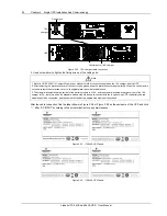
Warning
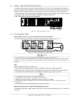
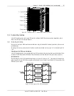
1. The parallel address for each UPS must be unique.
2. The default setting of all the DIP switches are OFF. However, you should set the DIP switch position for the parallel system
according to the descriptions listed in Table 3-1. Otherwise, a UPS fault will occur.
3. When one group of batteries supply power to several UPSs at the same time, the UF-BSO-0050 ITA UPS battery shared module
is essential, or else, the UPSs cannot share the battery. For the details of the battery shared module, refer to
UF-BSO-0050 ITA
UPS Battery Shared Module User Manual
.
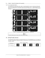
3.6 Commissioning Parallel System
3.6.1 Check Before Startup
1. Check and confirm that the power distribution mode of the main UPS is correct; that the connections of the power
cables and signal cables are correct and there is no short circuit. Check that the power distribution mode of the POD
and the cable connection are correct and there is no short circuit.
2. Check that the battery installation and cable connection are correct and there is no short circuit, and that the positive
pole and negative pole of the battery are correct.
3. Check that the phase sequence of the main, bypass and output of each UPS is correct and accordant. Ensure that
the parallel cable connection is reliable, and that the user load is not connected during power-on, to check all the
working status of the parallel system.
4. Measure and confirm that the mains voltage and frequency are normal.
5. The output terminals of the UPS and the POD are energized upon power-on. If the load is connected with the output
terminals, make sure that it is safe to feed power to the load.
3.6.2 Startup Commissioning For Parallel System
1. Power on and commission each UPS of the parallel system respectively, namely power on one UPS each time, and
other UPSs are in the turn-off status, the specific commissioning procedures are as follows:
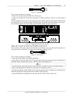
1) Close the external input MCB, output MCB, battery MCB and input MCB of one UPS, the UPS is powered on.
Ensure that other UPSs are in the turn-off status. (If POD is configured, close the corresponding input MCB and output
MCB of the POD).
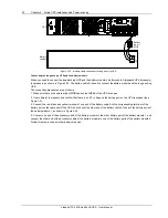
Warning
After the POD output MCB is closed, the UPS output terminal block, the POD output terminal block and the load will be live, pay
attention to personnel safety to avoid electrical shock. Confirm that it is safe to feed power to the load.
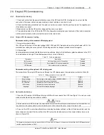
2) Power on the UPS to enter self-test status (including battery self-test), all LED indicators blink, and the buzzer
beeps at intervals. After the self-test, the UPS will enter the standby mode, and the mains indicator will turn on.
3) Press the ON/SILENCE key for more than one second, and wait for about thirty seconds, the UPS will transfer to
the inverter standby mode automatically, the inverter indicator blinks. After the UPS has output, the inverter indicator
will turn on.
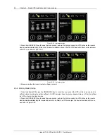
4) Measure that the inverter output voltage is normal.
5) If the UPS is working normally, turn off the UPS.
6) Repeat the preceding step1) ~ setp5) to power on and commission the other UPSs respectively.
Note
Carry out the parallel commissioning after each UPS is working normally.
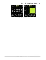
2. After confirming that each UPS has been powered on and is working normally, you can commission the parallel
system. The specific procedures are as follows:
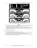
1) Close the external input MCB, output MCB, battery MCB and input MCB of one UPS (if POD is configured, close the
corresponding input MCB and output MCB of the POD), the UPS is powered on, at the same time, make sure that
other UPSs are in the turn-off status. After the self-test, press the ON/SILENCE key for one second, and wait for about