background image

4

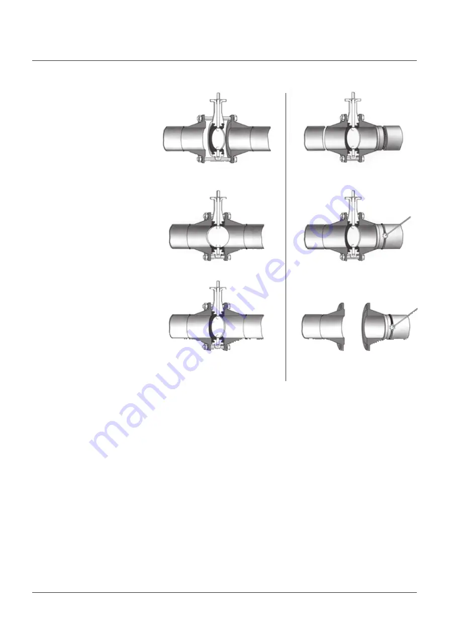
EXISTING SYSTEM

NEW SYSTEM

1.  Spread the flanges with the adequate tooling. 

Insert some flange bolts to hold the valve.

1.  Center a flange-valve-flange assembly between 

the pipes.

2. Open the valve and remove the flange spreads.

2. Tack weld the flanges to the pipes.

3.  Close the valve clockwise, return to open position 

and cross-tighten all bolting.

3.  Remove the valve and finish weld. 

Install the valve according to the procedure in the 

left column.

KEYSTONE

 SERIES 60 BUTTERFLY VALVES

INSTALLATION AND OPERATION MANUAL

FIGURE 2

3.5 Sources of possible danger

This section contains some examples of 
possible foreseen danger sources.

3.5.1 Mechanical

A.  When manual operators are used, available 

space should be checked in order to avoid 
hands being clamped.

B.  Mechanical sparks caused on impact of 

valve and e.g. tooling, are a potential source 
of ignition of surrounding atmosphere.

3.5.2 Electrical

If static charges or stray electrical currents 
can initiate explosions, the valve should be 
grounded to earth.

3.5.3 Thermal

A.  Isolation should be used on valves with 

application temperatures > +40°C (+104°F) 
and < -20°C (-4°F) to prevent them from 
being touched (to avoid burning).

B.  If the valve is used in hot gas/fluid 

applications that might give exothermic 
reactions, precautions must be taken so 
that the valve surface cannot lead to danger 
for people or the direct environment. In dust 
and possible explosion zones, the operation 
temperatures and ignition temperatures for 
dust should be reviewed.

3.5.4 Operational

Closing a valve too fast may result in water 
hammer in the upstream part of the pipeline. 
Water hammer results in excessive stresses in 
the valve and will cause severe damage.
Water hammer should be avoided in all 
circumstances.
Due to differential pressure across the valve 
disc, butterfly valves have the tendency to be 
closed by the flow. Take care when unlatching 
the valve operating mechanism.

Содержание KEYSTONE 60 Series

Страница 1: ... damage during handling the valves should be lifted by hand or using appropriate lifting equipment Do not fasten lifting devices around the valve operating shaft actuator or through the valve waterway The valve should be lifted with chains or slings which are fastened to rods or bolts which go through the bolt holes in the body flanges The valves should be protected from external events e g bumps ...

Страница 2: ...Materials of construction 3 2 Flange and pipe compatibility Check matching of flange drilling pattern of valve and pipe before assembly Flanges have to meet the following requirements see Figure 1 The face inside diameter should be D min The valve Q dimension adequate disc clearance D max The optimum inside diameter ID is equal to the inside diameter of flange standard ASME B16 5 table 8 Weld Neck...

Страница 3: ... Center the valve body and insert all flange bolts Tighten the flange bolts hand tight 5 Slowly open the valve completely The disc is in line with parallel flats or keyway in shaft head Keyway points towards disc edge 6 Maintain the valve flange alignment while gradually removing the flange spreaders and tighten the flange bolts hand tight 7 Slowly close and open the valve to check for adequate di...

Страница 4: ...on of surrounding atmosphere 3 5 2 Electrical If static charges or stray electrical currents can initiate explosions the valve should be grounded to earth 3 5 3 Thermal A Isolation should be used on valves with application temperatures 40 C 104 F and 20 C 4 F to prevent them from being touched to avoid burning B If the valve is used in hot gas fluid applications that might give exothermic reaction...

Страница 5: ...Figure 3 1 Clean all reusable parts 2 If valve has bearings 6 tap one in from top of valve neck flange until it is about 6 mm from top surface Tap the other in from inside the body seat bore into the bottom of the valve neck flange about 6 mm from the bottom surface 3 Apply a lubricant or soapy solution compatible with the elastomer to facilitate assembly 4 Insert liner 2 into body by pressing it ...

Страница 6: ...LUG DN 50 300 NPS 2 12 KEYSTONE SERIES 60 BUTTERFLY VALVES INSTALLATION AND OPERATION MANUAL PARTS LIST Item Description 1 Body 2 Liner 3 Disc 4 Upper shaft 5 Lower shaft 6 Bearing 7 Retaining pin PARTS LIST Item Description 1 Body 2 Liner 3 Disc 4 Upper shaft 5 Lower shaft 6 Bearing 7 Retaining pin FIGURE 3 Detail A Detail B Detail C Detail A Detail B Detail C ...

Страница 7: ...lean all reusable parts 2 Install the bearing 7 and 8 in the body Note the upper shaft bearing is longer of the two bearings drill the appropriate size hole through the upper shaft bearing at the retention screw hole in the body 1 for the retaining screw 9 3 Install liner 2 in the body 1 by locating the alignment rib on the liner with the alignment guide in the body and tapping the liner into the ...

Страница 8: ...er 3 Disc 4 Upper shaft 5 Lower shaft 6 Plug 7 Lower bearing 8 Upper bearing 9 Retaining screw 10 Thrust washer FIGURE 4 PARTS LIST Item Description 1 Body 2 Liner 3 Disc 4 Upper shaft 5 Lower shaft 6 Plug 7 Lower bearing 8 Upper bearing 9 Retaining screw 10 Thrust washer Topview SERIES 60 LUGGED DN 350 600 NPS 14 24 Detail B Detail A Detail B Detail A Detail B Detail A Detail B Detail C Detail C ...

Страница 9: ... 2017 Emerson All rights reserved ...

Отзывы: