Emerson FSD Скачать руководство пользователя страница 24

18 • FSD Installation and Operation Manual

026-1400 Rev 3 22-MAR-2011

7

E2 Ethernet Peer 

Communications

Communication between E2 controller version 

2.10 or greater may now be implemented through an 

Ethernet network using TCP/IP protocol. To utilize 

peer connections over Ethernet, the following tasks 

must be performed:

• Upgrade the E2 controller firmware to version 

2.10 or greater.

• Install an industry-standard Ethernet switch(es) 

or hub(s) in an area or areas nearby the E2 con-

trollers.

• Install Ethernet straight-through cabling at the 

site from each E2 to the switch or hub. Installa-

tion of RJ-45 connectors may be necessary to 

achieve this goal. The recommended cabling is 

CAT 5.

7.1. Ethernet IP 

Configurations

If using an open network configuration (see 

Sec-

tion 7.4.2., 

Open Network Layout

), contact your IT 

Network Administrator for all IP configuration infor-

mation (IP Address, Subnet Mask, Primary and De-

fault Gateway settings).
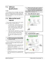
7.2. Hardware 

Specifications

Standard industry-accepted practices for wiring of 

Ethernet networks are expected. E2 controllers use a 

star topology, identical to PC deployment. This in-

cludes a unique “point-to-point” run from a switch or 

hub to the controller (see 

Table 7-1

 for hub part num-

bers for ordering). This is done with Category5 (or 

better) cable. Maximum distance for a run of 10BaseT 

is 328 feet (100 meters) (11.5 dB loss max). 

• The maximum number of controllers allowed 

on an IP subnet is 20. All E2 controllers that 

must communicate with each other must be on 

the same subnet.

• Recommended Ethernet cabling is CAT 5 

(straight-through cable).

• 328 feet (100 meters) is the maximum distance 

allowed between devices before a switch or hub 

must be added.

7.2.1. Components

Equipment 

Type

Specifications

Ethernet Five- or 
Nine-port Switch 
(may require an 
additional power 
supply)

* Industrial grade
* Operating/storage temp range: 

-40°F to 185°F 

* Vibration: IEC68-2-6
* RH: 5 to 95% 
* UL 508A, CE approved
* Supports 10Base-T crossover 

cable

* Supports all IEEE 802.3 protocol
* Supports Auto Crossover MDI/

MDI-X 

* Screw-terminal power connec-

tors

Ethernet Surge 
and Lightning 
Protector
(recommended)

* Industrial grade
* Surge capacity: 1 kA / line
*Operating temp range: -40°F to 

185°F

*Max frequency: 155 MHz
*Clamp and rated: 10V and 5V

10-Base-T/100-
Base-TX Hub

Room Temperature
(0 to 50 C)

P/N 570-0100

10-Base-T/100-
Base-TX Hub

Extended Temperature 
(-40 to 65 C) 

P/N 570-0200

Table 7-1

 - Equipment for E2 Ethernet Peer Communications

NOTE: An external power supply may be 
needed.

Содержание FSD

Страница 1: ...026 1400 Rev 3 22 MAR 2011 Facility Status Display FSD Installation and Operation Manual ...

Страница 2: ......

Страница 3: ... omission in this manual even if advised of the possibility of such damages In the interest of continued product development Computer Process Controls Inc reserves the right to make improvements to this manual and the products described herein at any time without notice or obligation CE FCC COMPLIANCE NOTICE Class A compliance for Facility Status Display under Part 15 of the FCC Rules and CE EN 55...

Страница 4: ......

Страница 5: ... 4 1 Alarms Tab 11 5 4 1 1 Show RTN Alarms 11 5 4 1 2 Show Reset Advisories 12 5 4 1 3 Display Asset Alarm 12 5 4 1 4 Show Notices 12 5 4 1 5 Filter Advisories 12 5 4 1 6 Sort Data Points 12 5 4 1 7 Audible Alarm 12 5 4 1 8 Snooze Delay 13 5 4 1 9 Min Alarm Priority 13 5 4 2 Communications Tab 13 5 4 2 1 E2 IP Address 13 5 4 2 2 E2 IP Port 13 5 4 2 3 Display Number 13 5 4 3 General Tab 13 5 4 4 Ab...

Страница 6: ...vi FSD Installation and Operation Manual 026 1400 Rev 3 22 MAR 2011 7 5 SOFTWARE SETUP 20 7 6 TROUBLESHOOTING 20 8 E2 ALARM ANNUNCIATOR SETUP 21 9 SOFTWARE UPDATES 21 10 SPECIFICATIONS 22 ...

Страница 7: ...ost convenient for the user The FSD can be configured to filter out notices and or return to normal alarms and provides a quick review of all advisories and detailed advisory infor mation The FSD also receives alerts and provides an nunciated alarms and alarm information directly to store and department managers This compact unit can be installed virtually anywhere with a standard Ethernet connect...

Страница 8: ...e 2 1 4 Step 4 Open the ferrite P N 090 0008 and run the Ethernet cable through wrapping the cable around the ferrite twice two turns near the Ethernet port LAN on the back of the display and close the ferrite Figure 2 2 around the Ethernet cable 5 Step 5 Plug the Ethernet cable into the RJ45 connector LAN on the back of the FSD s display module P N 750 5100 as indicated by Step 5 of Figure 2 3 6 ...

Страница 9: ...he mounting sur face 8 0 high by 9 0 wide by at least 3 875 deep 20 32 cm high by 22 86 cm wide by at least 9 84 cm deep When cutting the mounting hole allow at least 1 2 1 27 cm clearance around the hole for face plate mounting Figure 2 5 2 Once this hole is cut mount the unit as desired Figure 2 4 and position the enclo sure so that the four support tabs are flush against the outside lip of the ...

Страница 10: ...Leave 1 2 For Face Plate Mounting Open Side of Power Supply Box Mount Back Portion of FSD Power Supply Box Inside Wall 9 0 8 0 Support Tabs 4 3 875 Push out Tabs Conduit Knock outs Drawing Not To Scale Face Plate Screw Holes 4 Open Side of Power Supply Box 9 0 8 0 1 2 1 2 leave clearance each side for face plate 1 2 1 2 ...

Страница 11: ...T tab cursor down to Status Display and then enter the desired number of devices Figure 3 2 3 2 STEP 2 Set Up IP Address for the FSD DHCP is enabled by default If you have a DHCP server the FSD will retrieve an IP Address automati cally If you wish to set up a static IP Address follow these steps 1 Touch the tool icon and enter the pass code on the security screen default code is 400 as shown in F...

Страница 12: ...SD will communicate with must be en tered When the FSD is powered up for the first time the Start up or Boot Loader screens will appear 1 Log on by entering the passcode default code is 400 into the blank field on the first boot loader screen Figure 3 5 and touch Configure Touching the inside of this field will toggle the virtual keyboard 2 On the second boot loader screen Figure 3 6 enter the IP ...

Страница 13: ...alarm with visible countdown timer if Snooze is enabled until audible alarms is reactivated The audible alarm will annunciate any time there is an active alarm displayed on the alarm If alarming or Snoozing is active and the filtered alarm list indi cates that no alarm is active any active state alarm or Snooze will be canceled automatically Automatic color coding allows for simple differ entiatio...

Страница 14: ...enerated the UP arrow will scroll up to the previous alarm Touching the DOWN arrow will scroll down to the next alarm in the list 5 2 Alarm List Screen The Alarm List screen shows all filtered alarms in a list called the alarm log Multiple alarm entries are shown with a scroll bar to navigate through the alarm list UP and DOWN arrows will page up and page down on this screen ICON ACTION Displays t...

Страница 15: ...ormation and if available the limit that was exceeded 5 3 Data Points Screen The Data Points screen is a view only screen that shows the list of all data points being monitored by the FSD In Figure 5 4 the Data Points screen name is dis played across the top of the screen in this example it is called Department Status This name is config ured under the Status Title parameter under FSD General Setu...

Страница 16: ...es are active If no data point is selected when the details icon is touched a reminder will appear If a pointer has not been defined in the E2 applica tion a three dash result will appear If this three dash value is selected and the details icon is touched the following message will appear Figure 5 5 Detailed Data Point Information Figure 5 6 Detailed Information if the Data Point Failed Figure 5 ...

Страница 17: ...iguring param eters Touch OK to save and exit to the Home screen Cancel to discard changes and exit to the Home screen 5 4 1 Alarms Tab Configure alarm information on the Alarms tab with the following parameters Show RTN Alarms Show Reset Advisories Display Asset Alarm Show Notices Filter Advisories Sort Data Points Audible Alarm settings Set snooze delay in minutes Set minimum alarm priority Thes...

Страница 18: ...ow Notices This notice setting determines whether the FSD will display notices along with other types of adviso ries or whether these notices will be filtered out of the FSD Enable this box to show Notices in the alarm list uncheck to filter out 5 4 1 5 Filter Advisories This setting causes the FSD to display only advi sory information of points that are included in the monitored data point list A...

Страница 19: ...The FSD will point only to a single E2 at a site it will not poll multiple controllers for alarms For multiple E2s at a site enter the IP address of the alarm annunciator E2 If one E2 is located at a site enter the IP address for that single E2 5 4 2 2 E2 IP Port The E2 IP Port is the port number used by the FSD to connect with the E2 unit The port number in this field must match the FSD Client Po...

Страница 20: ...utomatically if the device is idle for more than 10 minutes To change the backlight setting 1 Touch the tool icon and enter the pass code on the security screen as shown in Fig ure 5 10 2 Select the General tab and touch the Exit Application button Figure 5 17 3 A loader screen will appear Figure 5 18 Touch Exit Loader at the top right of the screen 4 The desktop screen will appear Figure 5 19 Pre...

Страница 21: ...n off backlight while on external power setting and from the drop down list choose when the backlight will automatically turn off 6 To save your settings touch and drag the Display Properties window to the left until you see OK in the upper right corner Touch OK to save and return to the desktop screen Figure 5 20 Display Properties Window Backlight Settings ...

Страница 22: ...nd string values for the Title Data Point in the Title Data Pt and Title Data Str fields respectively This will change the default Title Data Point details on the FSD Data Point screen Figure 5 4 If the Title Data Point parameters are not changed the FSD Data Points screen will use the default values set for these parameters i e the Global Data s OAT 6 Press F2 Next Tab to go the Data Pts setup an...

Страница 23: ... Communications 8 Go to the Pts Names tab and enter a name for the data point Figure 6 4 A point name is the unique name given to the data point specified by the user and will be displayed on the FSD screen 9 After entering the data point enter a unique name in the Data Name field on this screen If no name is assigned the data point will be displayed in the default Controller Application Property ...

Страница 24: ...oint to point run from a switch or hub to the controller see Table 7 1 for hub part num bers for ordering This is done with Category5 or better cable Maximum distance for a run of 10BaseT is 328 feet 100 meters 11 5 dB loss max The maximum number of controllers allowed on an IP subnet is 20 All E2 controllers that must communicate with each other must be on the same subnet Recommended Ethernet cab...

Страница 25: ...s network type is used if the network will be connected to the store s LAN The E2 peer Ethernet network facilitates commu nications between E2 controllers These include at least the following Routing of messages between external entities such as UltraSite InSite Site Manager and non gateway E2 controllers Distribution of global data and other network variables such as system time controller identi...

Страница 26: ...etwork Administrator for any additional information needed NOTE DHCP does not have to be enabled if you have the IP Address Subnet Mask and Primary Gateway settings Contact your IT Network Administrator for all IP configuration information If you do not have the IP configuration settings and there is a DHCP server on the network set DHCP Enabled to Yes and it will retrieve the informa tion from th...

Страница 27: ...t only one alarm annunciator per network is al lowed To set up from the Main Menu 1 Press System Configuration 2 Press System Information 3 Press General Controller Info 4 Set Alarm Annunc field to Yes 9 Software Updates Updates to FSD application functionality will au tomatically be synched with the update of E2 s firm ware Any software the device runs will be retrieved from the configured E2 Fig...

Страница 28: ...5 Transformer Output to Circuit Board 24VAC Maximum Current 1 0 amp Humidity 10 to 95 104 F 40 C relative humidity non condensing Operating Temp 32 to 122 F 0 to 50 C Storage Temp 4 to 140 F 20 to 60 C Dimensions Screen diagonal 3 5 Flush mounting plate 9 x 10 Mounting hole 9 x 8 Table 10 1 Facility Status Display Specifications ...

Отзывы: