


Instruction Manual
D102603X012
667NS Actuator
June 2018
3
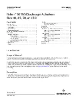
Table 5. Size 80 Diaphragm Area
TRAVEL
AREA
mm
Inch
cm
2
Inch
2
0
19
29
38
0
0.75
1.125
1.5
2039
1903
1865
1845
316
295
289
286
51
64
76
2
2.5
3
1832
1800
1761
284
279
273
Specifications
Tables 1 and 2 provide specifications for the various sizes of 667NS actuators discussed in this instruction manual.
WARNING
To avoid personal injury or property damage, do not exceed pressure and temperature limits specified in table 1.
Educational Services
For information on available courses for the Fisher 667NS diaphragm actuator, as well as a variety of other products,
contact:
Emerson Automation Solutions
Educational Services - Registration
Phone: 1-641-754-3771 or 1-800-338-8158
E-mail: [email protected]
emerson.com/fishervalvetraining
Maximum Pressure Limitations
The casing and diaphragm of 667 actuators are pressure operated. This air pressure provides energy to compress the
spring, to stroke the actuator, and lift the diaphragm away from the valve. The following explanations describe the
maximum pressure limits for an actuator. Refer to table 1 for maximum values.
WARNING
To avoid personal injury or property damage, do not exceed pressure and temperature limits specified in table 1.
D
Maximum Diaphragm Pressure to Stroke the Actuator:
This is the maximum pressure that can be applied at less
than full travel of the actuator. If this stroking pressure is exceeded before the upper diaphragm plate contacts the
travel stop, damage to the stem or other parts might result.


