


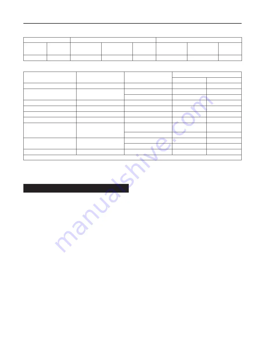
Table 3.
Flow Coefficients
ORIFICE
NPS 1 / DN 25 BODY
NPS 2 / DN 50 BODY
In.
mm
Wide-Open C
g
for
External Relief Sizing
Wide-Open C
v
for
External Relief Sizing
C
1
Wide-Open C
g
for
External Relief Sizing
Wide-Open C
v
for
External Relief Sizing
C
1
9/16
14.3
211.6
5.6
37.8
219.3
6.0
36.0
Table 4.
Maximum Torque Values
KEY NUMBER
(1)
COMPONENT
CONSTRUCTION
MAXIMUM TORQUE
Ft-lbs
N•m
2
Orifice
All
25 to 35
33.9 to 47.5
3
Cap screw, Body
Aluminum lower casing
10 to 20
13.6 to 27.1
Ductile Iron or Steel lower casing
22 to 30
29.8 to 40.7
9
Disk Holder Assembly
All
20 to 24 in-lbs
2.3 to 2.7
18
Cap screw, Lever
All
7 to 10
9.5 to 13.6
22
Nut, Diaphragm Connector
627BMR
15 to 20
20.3 to 27.1
26
Guide Retainer
627BMR
2.5 to 4
3.4 to 5.4
37
Cap screw, Spring Case
Ductile Iron or
Aluminum lower casing
7 to 10
9.5 to 13.6
Steel lower casing
36 to 40
48.8 to 54.2
46
Cap screw, Diaphragm Head
627BM
7 to 10
9.5 to 13.6
627BHM
12 to 16
16.3 to 21.7
78
Spring Seat Retainer
All
55 to 60 in-lbs
6.2 to 6.8
1. Refer to Figures 6 through 8 for key number locations.
Startup and Adjustment
Startup
▲
WARNING
To avoid personal injury or property damage
due to explosion or damage to regulator or
downstream components during startup,
release downstream pressure to prevent an
overpressure condition on the diaphragm of
the regulator.
In order to avoid an overpressure condition and
possible equipment damage, pressure gauges
should always be used to monitor pressures
during startup.
1. Slowly open the upstream shut-off valve.
2. Slowly open the downstream shut-off valve.
3. Check all connections for leaks.
4. Make final control spring adjustments according to the
adjustment procedures.
Adjustment
The range of allowable pressure settings is marked on the
nameplate. If a pressure setting beyond this range is necessary,
substitute the appropriate regulator control spring. Change the
nameplate to indicate the new pressure range.
Before increasing the setting, refer to Table 1 or 2. Review the
pressure limits for the control spring range being used and
be certain that the new pressure setting will not result in an
overpressure condition.
Note
Always use a pressure gauge to monitor
pressure when making adjustments.
Refer to Figures 6 through 8 for key number locations.
1. Remove the adjusting screw cap (key 36).
2. Loosen the locknut (key 34).
3. Increase the outlet pressure setting by turning the adjusting
screw (key 35) clockwise. Decrease the outlet pressure
setting by turning the adjusting screw counterclockwise.
4. When the desired pressure is obtained, hold the adjusting
screw (key 35) in place and tighten the locknut (key 34).
5
627B Series