background image

249W Level Sensor

Instruction Manual

Form 5729
March 2005

3

Type Number Description

D

Type 249W—3- or 4-inch, ANSI Class 150,

300, 600 steel cageless sensor.

The Parts List section shows some Type 249W
constructions, standard displacer lengths, and
standard materials. However, Type 249W parts are
available in a wide variety of materials of
construction, part dimensions, and other
specifications. Contact your Fisher sales office for
assistance in selection of specific materials,
dimensions, and specifications.

Installation

WARNING

To avoid personal injury or property
damage resulting from the sudden
release of pressure:

D

Always wear protective clothing

and eyewear when performing any
installation operations to avoid
personal injury.

D

Check with your process or safety

engineer for any additional measures
that must be taken to protect against
process media.

D

If installing into an existing

application, also refer to the WARNING
at the beginning of the Maintenance
section of this instruction manual.

The Type 249W sensor can be installed directly on
the vessel as shown in figure 4. It also can be
installed in a user fabricated cage mounted on the
side of the vessel as shown in figure 5. The sensor
mounts on the top of the vessel or in the displacer
cage using a 3-inch raised face flange with the
3-inch 249W wafer body, or a 4-inch raised-face
flange with the 4-inch 249W wafer body.

Installation on Top of Vessel

CAUTION

If a stillwell is used, install it plumb so
that the displacer does not touch the
wall of the stillwell. If the displacer
touches the wall, the unit will transmit
an erroneous output signal.

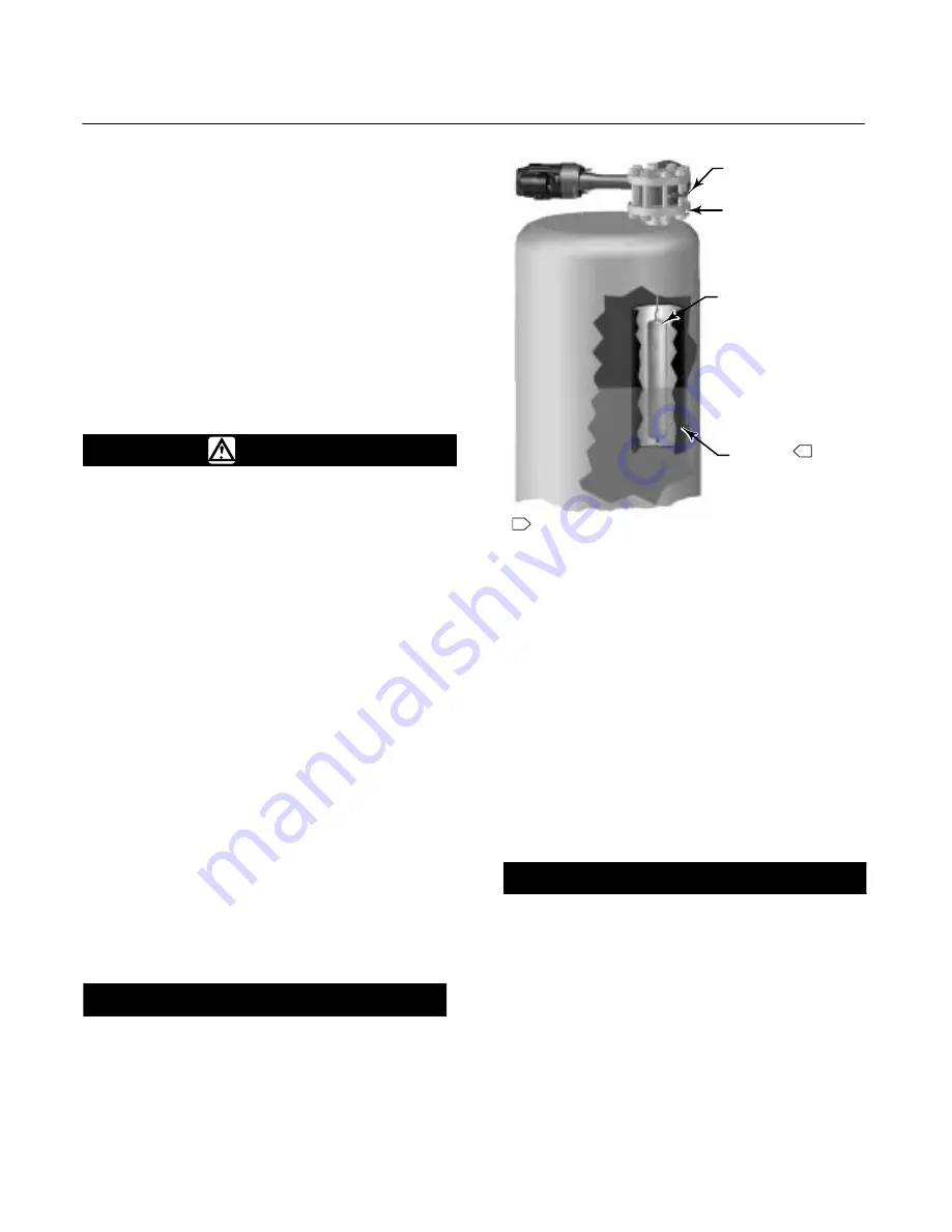
Figure 4. Type 249W Sensor Top Mounted on Vessel

TYPE 249W WAFER BODY

3- OR 4 - INCH
RF FLANGE

DISPLACER

STILLWELL

1

1

NOTE:

STILLWELL REQUIRED AROUND DISPLACER IF THE FLUID

IS IN A STATE OF CONTINUOUS AGITATION

W8266 / IL

Because the displacer hangs inside the vessel,
provide a stillwell around the displacer if the fluid is
in a state of continuous agitation to avoid excessive
turbulence around the displacer.

To attach the sensor body to the vessel requires a
flanged connection on the vessel as shown in figure
4. For interface or fluid level applications, install a
gauge glass on the vessel.

Installation with Displacer Cage on
Side of Vessel

CAUTION

Install the cage so that it is plumb; the
displacer must not touch the cage
wall. If the displacer touches the cage
wall, the unit will transmit an
erroneous output signal.

Figure 5 shows the Type 249W sensor mounted on
the side of a vessel using a displacer cage. Figures
6, 7, 8, and 9 provide the Type 249W dimensions
required to fabricate a cage. Figure 10 provides
overall envelope dimensions for Type 249W sensor
and DLC3010 controller.

Содержание Fisher 249W

Страница 1: ...ler or transmitter as shown in figure 1 this manual does not include operation installation calibration maintenance and parts ordering information for the controller transmitter or for the complete unit For this information refer to the appropriate controller transmitter instruction manual Figure 1 Type 249W Sensor with DLC3000 Series Digital Level Controller W8231 IL No person may install operate...

Страница 2: ... packing friction The displacer always exerts a downward force on one end of the displacer rod The other end of the displacer rod rests on the knife edge of the driver bearing A keyed shaft on the bearing end of the displacer fits into a socket on the outside of the welded end of the torque tube assembly A change in liquid level interface level or density specific gravity buoys up the displacer by...

Страница 3: ...cer cage using a 3 inch raised face flange with the 3 inch 249W wafer body or a 4 inch raised face flange with the 4 inch 249W wafer body Installation on Top of Vessel CAUTION If a stillwell is used install it plumb so that the displacer does not touch the wall of the stillwell If the displacer touches the wall the unit will transmit an erroneous output signal Figure 4 Type 249W Sensor Top Mounted...

Страница 4: ...LANGE BLIND FLANGE FOR SCREWED OR SOCKET WELD CONNECTIONS 3 OR 4 INCH CLASS 150 300 OR 600 FLANGE FS1 ÇÇ F 73 2 87 E0726 IL mm INCH Figure 7 Cage Dimensions for Style 2 Cage Top and Lower Side Connections G FLANGE ADAPTOR REQUIRED IF FLANGE CONNECTIONS ARE OTHER THAN 3 INCH 3 OR 4 INCH CLASS 150 300 OR 600 FLANGE BLIND FLANGE FOR SCREWED OR SOCKET WELD CONNECTIONS 3 OR 4 INCH CLASS 150 300 OR 600 ...

Страница 5: ...lines Also install a drain between the cage and shutoff or hand valve whenever the bottom cage line has a fluid trapping low point On fluid or interface level applications position the displacer cage so that the cage center is as close as possible to the center of the fluid level or interface level range being measured Also consider installing a gauge glass on the vessel or on the displacer cage F...

Страница 6: ...mer Supplied Cage RIGHT HAND MOUNT LEFT HAND MOUNT A A 501 19 73 204 8 04 204 8 04 507 19 75 610 24 00 A SIZE 3 4 mm Inch 127 157 5 00 6 19 73 2 87 73 2 87 G G F F D D j j END VIEW OF INSTRUMENT HEAT INSULATOR EXTENSION 1 2 14 NPT 2 PLACES 66 2 61 59 2 34 59 2 34 139 5 49 NOTE DIMENSIONS D F AND G ARE CUSTOMER SPECIFIED DIMENSIONS 10C0786 B ...

Страница 7: ... 67 115 15 845 124 190 28 1111 111 250 25 1 Torque values for NCF2 without additional lubricant are equal to Molykote 321R 1 Place the seal on the connecting flange To install the displacer insert the displacer in the vessel or cage Hold the wafer body above the connecting flange Connect the displacer as shown in figure 12 locking the assembly with the cotter springs provided If a stem extension i...

Страница 8: ...nstalled D Drain the process liquid from the process vessel D Shut off any electrical or pneumatic input to the controller or transmitter attached to the Type 249W sensor and vent any pneumatic supply pressure D Use caution when loosening flange bolting or pipe plugs D Remove the controller or transmitter from the torque tube arm key 2 Before performing any maintenance procedure requiring the hand...

Страница 9: ...s been penetrated by process pressure Figure 14 Type 249W Installation Complete W8227 or liquid it may hold pressure or hazardous liquid for an extended period Process residue buildup on the displacer and stem key 11 may change displacer weight or displacement A bent stem or a dented or corroded displacer can impair performance If the displacer rests against the travel stop appears to be overweigh...

Страница 10: ...cessary CAUTION If the displacer is to be disconnected from the displacer rod before being removed from the process vessel or displacer cage provide a suitable means of supporting the displacer to prevent it from dropping into the vessel or cage and being damaged 1 After following the proper procedure to remove the sensor and the displacer from the process vessel or displacer cage move the sensor ...

Страница 11: ...oid damage to the displacer displacer stem displacer rod assembly and associated parts 2 Remove the controller transmitter and displacer key 4 Then remove the hex nuts key 20 that hold the torque tube arm key 2 to the wafer body key 1 Separate the torque tube arm from the wafer body 3 Remove the nuts key 18 and retaining flange key 14 holding the positioning plate key 15 at the end of the torque t...

Страница 12: ...displacer rod assembly and associated parts 2 Remove the controller transmitter and displacer key 4 Then remove the hex nuts key 20 that hold the torque tube arm key 2 to the wafer body key 1 Separate the torque tube arm from the wafer body 3 Follow the proper procedure to remove the torque tube assembly key 3 4 Remove the driver bearing bolts key 8 displacer rod driver assembly key 5 and driver b...

Страница 13: ...affect the performance of the valve and might jeopardize worker and workplace safety Determining Displacer Stem Length When ordering a displacer stem determine the displacer stem length from the G dimension in figures 8 and 9 cage styles 3 and 4 For cage styles 1 and 2 the G dimension is typically 0 so no stem is required The stem length will be the G dimension rounded to the nearest 1 2 inch incr...

Страница 14: ...WCC steel 1K4493X0012 316 SST std w CF8M 1K4503000A2 N06600 1K4515000A2 N10276 1K4527000A2 Thin wall N05500 std w WCC steel 1K4495X0012 316 SST std w CF8M 1K4505000A2 N06600 1K4517000A2 N10276 1K4529000A2 Heavy wall N05500 std w WCC steel 1K4497X0012 316 SST std w CF8M 1K4541000A2 N06600 1P8662X0012 N10276 1K453140152 Recommended spare parts 1 This part is available in a wide variety of materials ...

Страница 15: ...c inches 3 75 pounds 1400 psi S30400 15A5107X022 S31600 15A5107X032 1 1 4 x 84 inches 103 cubic inches 4 75 pounds 1800 psi S30400 15A5104X042 S31600 15A5104X052 Key Description Part Number 4 Displacer 1 cont d 1 1 8 x 96 inches 95 cubic inches 4 75 pounds S30400 1570 psi 15A5102X042 S31600 2100 psi 15A5102X052 1 1 8 x 108 inches 107 cubic inches 4 75 pounds 1600 psi S30400 1C1688000A2 S31600 1C16...

Страница 16: ...r Marshalltown Iowa 50158 USA Cernay 68700 France Sao Paulo 05424 Brazil Singapore 128461 Emerson Process Management www Fisher com The contents of this publication are presented for informational purposes only and while every effort has been made to ensure their accuracy they are not to be construed as warranties or guarantees express or implied regarding the products or services described herein...

Отзывы: