


Digitax ST User Guide
55
Issue: 5
(%)
Where:
T
R
Required maximum torque
T
RATED
Motor rated torque
Alternatively, set 0.06 at the required maximum active (torque-
producing) current as a percentage of the rated active current of the
motor, as follows:
(%)
Where:
I
R
Required maximum active current
I
RATED
Motor rated active current
Pr
0.07
(
3.10
) operates in the feed-forward path of the speed-control
loop in the drive. See Figure 12-3 on page 124 for a schematic of the
speed controller. For information on setting up the speed controller
gains, refer to Chapter 8
.
Pr
0.08
(
3.11
) operates in the feed-forward path of the speed-control
loop in the drive. See Figure 12-3 on page 124 for a schematic of the
speed controller. For information on setting up the speed controller
gains, refer to Chapter 8
.
Pr
0.09
(
3.12
) operates in the feedback path of the speed-control loop in
the drive. See Figure 12-3 on page 124 for a schematic of the speed
controller. For information on setting up the speed controller gains, refer
to Chapter 8
.
Pr
0.10
(
3.02
) indicates the value of motor speed that is obtained from
the speed feedback.
Pr
0.11
displays the position of the encoder in mechanical values of 0 to
65,535. There are 65,536 units to one mechanical revolution.
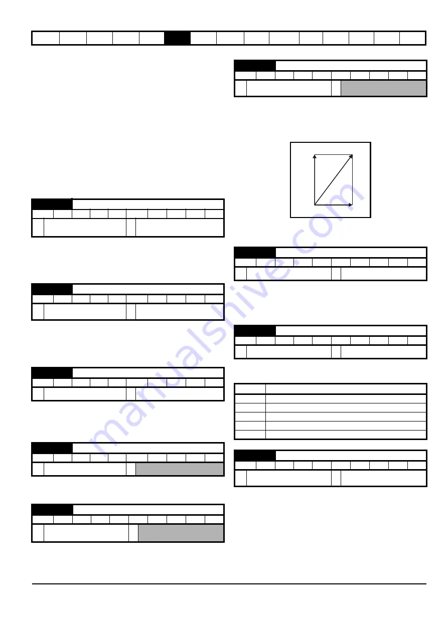
Pr
0.12
displays the rms value of the output current of the drive in each
of the three phases. The phase currents consist of an active component
and a reactive component, which can form a resultant current vector as
shown in the following diagram.
The active current is the torque producing current and the reactive
current is the magnetising or flux-producing current.
Pr
0.13
can be used to trim out any offset in the user signal to analog
input 1.
6.2.4 Jog reference, Ramp mode selector, Stop and
torque mode selectors
Pr
0.14
is used to select the required control mode of the drive as
follows:
Pr
0.15
sets the ramp mode of the drive as shown below:
0: Fast ramp
Fast ramp is used where the deceleration follows the programmed
deceleration rate subject to current limits. This mode must be used if a
braking resistor is connected to the drive.
1: Standard ramp
Standard ramp is used. During deceleration, if the voltage rises to the
standard ramp level (Pr
2.08
) it causes a controller to operate, the output
of which changes the demanded load current in the motor. As the
controller regulates the DC bus voltage, the motor deceleration increases
as the speed approaches zero speed. When the motor deceleration rate
0.07 {3.10}
Speed controller proportional gain
RW
Uni
US
Ú
0.0000 to 6.5535
1/rad s
-1
Ö
0.0100
0.08 {3.11}
Speed controller integral gain
RW
Uni
US
Ú
0.00 to 655.35
1/rad
Ö
1.00
0.09 {3.12}
Speed controller differential feedback gain
RW
Uni
US
Ú
0.00000 to 0.65535(s)
Ö
0.00000
0.10 {3.02}
Motor speed
RO
Bi
FI
NC
PT
Ú
±SPEED_MAX rpm
Ö
0.11 {3.29}
Drive encoder position
RO
Uni
FI
NC
PT
Ú
0 to 65,535
1/2
16
ths of a revolution
Ö
0.06
[
]
T
R
T
RATED
--------------------
100
×
=
0.06
[
]
I
R
I
RATED
-------------------
100
×
=
0.12 {4.01}
Total motor current
RO
Uni
FI
NC
PT
Ú
0 to
DRIVE_CURRENT_MAX A
Ö
0.13 {7.07}
Analog input 1 offset trim
RW
Bi
US
Ú
±10.000 %
Ö
0.000
0.14 {4.11}
Torque mode selector
RW
Uni
US
Ú
0 to 4
Ö
Speed control (0)
Setting
Function
0
Speed control
1
Torque control
2
Torque control with speed override
3
Coiler/uncoiler mode
4
Speed control with torque feed-forward
0.15 {2.04}
Ramp mode select
RW
Txt
US
Ú
FASt (0)
Std (1)
Ö
Std (1)
Active
current
Total current
Magnetising current
Содержание Digitax ST
Страница 1: ...User Guide AC variable speed drive for servo motors Part Number 0475 0001 05 Issue 5 ...
Страница 209: ......
Страница 210: ...0475 0001 05 ...


