


C6.2.41/0219/E
11
In such a case an accumulator must be used to reduce flood-back to a safe level that the
compressor can handle. The use of accumulators is dependent on the application. If an
accumulator must be used, the oil-return orifice should be from 1 to 1.4 mm in diameter for all
ZR*KRE models, depending on compressor size and compressor flood-back results.
The size of the accumulator depends upon the operating range of the system and the amount of
subcooling and subsequent head pressure allowed by the refrigerant control.
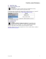
3.5
Screens
CAUTION
Screen blocking! Compressor breakdown!
Use screens with at least
0.6 mm openings.
The use of screens finer than 30 x 30 mesh (0.6 mm openings) anywhere in the system should be
avoided with these compressors. Field experience has shown that finer mesh screens used to
protect thermal expansion valves, capillary tubes, or accumulators can become temporarily or
permanently plugged with normal system debris and block the flow of either oil or refrigerant to
the compressor. Such blockage can result in compressor failure.
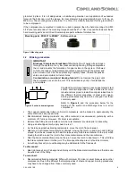
3.6
Mufflers
External mufflers, normally applied to piston compressors in the past, may not be required for
Copeland Scroll compressors.
Individual system tests should be performed to verify acceptability of sound performance. If
adequate attenuation is not achieved, use a muffler with a larger cross-sectional area to inlet area
ratio. A ratio of 20:1 to 30:1 is recommended.
A hollow shell muffler will work quite well. Locate the muffler at minimum 15 to maximum 45 cm
from the compressor for the most effective operation. The further the muffler is placed from the
compressor within these ranges, the more effective. Choose a muffler with a length of 10 to
15 cm.
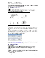
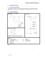
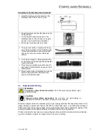
3.7
Suction line noise and vibration
Copeland Scroll compressors inherently have low
sound and vibration characteristics. However in
some
respects
the
sound
and
vibration
characteristics differ from reciprocating compressors
and in rare instances could result in unexpected
sound generation. One difference is that the vibration
characteristic of the scroll compressor, although low,
includes two very close frequencies, one of which is
normally isolated from the shell by the suspension of
an
internally-suspended
compressor.
These
frequencies, which are present in all compressors,
may result in a low-level "beat" frequency that can be
detected as noise coming along the suction line into
the building under some conditions. Elimination of
the beat can be achieved by attenuating either of the
contributing frequencies. This is easily done by using
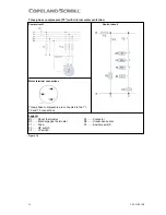
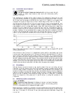
one of the common combinations of recommended design configurations. The scroll compressor
makes both a rocking and twisting motion and enough flexibility must be provided in the line to
prevent vibration transmission into any lines attached to the unit. In a split system, the most
important goal is to ensure minimal vibration in all directions at the service valve to avoid
transmitting vibrations to the structure to which the lines are fastened.
A second difference of the Copeland Scroll is that under some conditions the normal rotational
starting motion of the compressor can transmit an "impact" noise along the suction line. This may
be particularly pronounced in three-phase models due to their inherently higher starting torque.
This phenomenon, like the one described previously, also results from the lack of internal
suspension and can be easily avoided by using standard suction line isolation techniques as
described below.
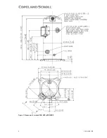
Figure 8: Suction tube design