background image

1

© 2014 Emerson Climate Technologies, Inc.
Printed in the U.S.A.

AE4-1317 R10

Application Engineering

B

U

L

L

E

T

I

N

AE4-1317 R10

April 2014

Application Engineering 

B

U

L

L

E

T

I

N


Application Guidelines for ZBKC / ZBKCE 

Refrigeration Copeland Scroll

 Compressors 1.3 to 7.5 HP

Safety
 Safety 

Instructions 

...................................................2

  Safety Icon Explanation ..........................................2
  Instructions Pertaining to Risk of Electrical Shock,
   Fire, or Injury to Persons ........................................3
 Safety 

Statements 

...................................................3 

Introduction ................................................................ 4
Nomenclature ............................................................ 4
Operating Envelope ................................................... 4
Accumulators ............................................................. 4
Crankcase Heaters .................................................... 4
Discharge Line Thermostat ....................................... 4
Pressure Controls ...................................................... 5
Pump Down Recommendations ................................ 5
IPR Valve  .................................................................. 5
Internal Temperature Protection  ............................... 5
Motor Protection ........................................................ 5
Oil Types .................................................................... 5
Oil Charges................................................................ 6
Oil Management for Rack Applications...................... 6
Compressor Tubing and Mounting ............................ 6
Mounting for Rack Systems....................................... 6
Condensing Unit Mounting ........................................ 6
Starting Characteristics ............................................. 6
Fusite ......................................................................... 7
Shell Temperature ..................................................... 7
Connection Fittings .................................................... 7
Three-Phase Rotation Direction ................................ 7
Brief Power Interruptions ........................................... 7
Deep Vacuum Operation ........................................... 7
Unbrazing System Components ................................ 7
High Potential (Hipot) Testing .................................... 7
Copeland Scroll


Functional Check ............................. 8

TABLE OF CONTENTS

Section                                                                            Page    Section                                                                                  Page

Figures

ZB*KCE Application Envelopes ..................................9
Scroll Rack Mounting................................................10
Scroll Condensing Unit Mounting .............................10
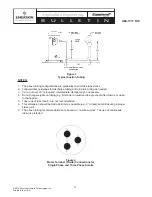
Typical Suction Tubing..............................................11
Motor Terminal (Fusite) Connections for Single
  Phase and Three Phase Scrolls .............................11
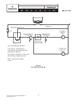
Scroll Wiring Schematic............................................12

Tables

Compressor Models and Approved Refrigerants/
  Lubricants ...............................................................13
Charge Limitations....................................................13
Crankcase Heater.....................................................14
Conduit Ready Heater Terminal Box Kits .................14
Discharge Thermostat Line Kits ...............................14
Pressure Control Settings.........................................14
Check-Valve Type .....................................................15
Recommended Oil Charges by Model Family ..........15

Содержание Copeland Scroll ZBKC

Страница 1: ...plications 6 Compressor Tubing and Mounting 6 Mounting for Rack Systems 6 Condensing Unit Mounting 6 Starting Characteristics 6 Fusite 7 Shell Temperature 7 Connection Fittings 7 Three Phase Rotation Direction 7 Brief Power Interruptions 7 Deep Vacuum Operation 7 Unbrazing System Components 7 High Potential Hipot Testing 7 Copeland Scroll Functional Check 8 TABLE OF CONTENTS Section Page Section P...

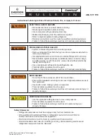
Страница 2: ...hout the lifetime of the compressor You are strongly advised to follow these safety instructions Safety Icon Explanation DANGER indicates a hazardous situation which if not avoided will result in death or serious injury WARNING indicates a hazardous situation which if not avoided could result in death or serious injury CAUTION used with the safety alert symbol indicates a hazardous situation which...

Страница 3: ...n oils Personal safety equipment must be used Failure to follow these warnings could result in serious personal injury BURN HAZARD Do not touch the compressor until it has cooled down Ensure that materials and wiring do not touch high temperature areas of the compressor Use caution when brazing system components Personal safety equipment must be used Failure to follow these warnings could result i...

Страница 4: ...imum of 20 F 11 C superheat measured on the suction line 6 inches 152mm from the suction valve to prevent liquid refrigerant floodback Another method to determine if liquid refrigerant is returning to the compressor is to accurately measure the temperature difference between the compressor oil crankcase and the suction line During continuous operation we recommend that this difference be a minimum...

Страница 5: ...is locatedrightatthesuctioninletofthecompressor it will be more sensitive to pressure spikes 2 Actual low pressure setting Refer to our recommended setting in Table 5 If the differential pressure setting is too close this will increase the possibility of short cycling 3 Type of Low pressure control can have an effect oncycling Theencapsulatednon adjustabletype is more susceptible to causing excess...

Страница 6: ...tion and tubing reliability Some tubing geometry or shock loops may be required to reduce vibration transferred from the compressor to external tubing Mounting for Rack Systems For 1 3 7 5 HP compressors specially designed rubber grommets are available for refrigeration scroll compressor applications These grommets are formulated from a durometer material specifically designed for refrigeration ap...

Страница 7: ...shell and suction line tubing pressurized If a brazing torch is then applied to the low side the pressurized refrigerant oil mixture could ignite as it escapes and contacts the of start assist devices in most applications However if low voltage conditions exist at start up protector trips can result Therefore start assist devices start capacitorsandrelays areavailabletomaximizestarting characteris...

Страница 8: ...ltage 2 Normal motor winding continuity and short to ground checks will determine if the inherent overload motor protector has opened or if an internal short to ground has developed If the protector has opened the compressor must cool sufficiently to reset 3 With service gauges connected to suction and discharge pressure fittings turn on the compressor Ifsuctionpressurefallsbelownormal levels the ...

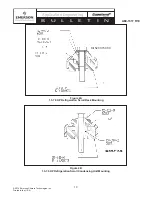
Страница 9: ...ompletely around the joint Slowly move torch inArea 3 to draw braze material into the joint Do not overheat joint 1 2 3 Scroll Tube Brazing Figure 1A ZB KCE Application Envelope for R 404A R 507 1 3 7 5 HP p 10 50 10 120 10 140 45 140 45 80 15 50 10 50 10 120 10 140 15 140 10 100 10 120 40 60 80 100 120 140 160 20 10 0 10 20 30 40 50 60 Condensing Temperature F Evaporating Temperature F 65 F Retur...

Страница 10: ...chnologies Inc Printed in the U S A AE4 1317 R10 Application Engineering B U L L E T I N Figure 2A 1 3 7 5 HP Refrigeration Scroll Rack Mounting Figure 2B 1 3 7 5 HP Refrigeration Scroll Condensing Unit Mounting Kit 527 0157 00 ...

Страница 11: ...ediate clamps may be necessary 4 Do not hang weights on tubing e g filter drier on suction tubing except after clamps or close to the header 5 Tube runs of less than 8 are not recommended 6 This dimension should be made as short as possible e g 2 or less but still insuring a proper braze joint 7 The above tubing recommendations are based on no elbow joints The use of continuous tubing is preferred...

Страница 12: ...ne Thermostat Compressor Contactor Coil Other Protective Devices if used System Operating Thermostat Fuse Optional Condenser Fan Contactor Coil if used Time Delay Relay Specifications Timer Opens 1 Electrical Cycle 016 Seconds with 60 HZ Operation After Power is Removed Timer Closes 2 Minutes 20 Later Whether Power is Restored or Not CSR Current Sensing Relay Contact 230 240 VAC C2 C1 ...

Страница 13: ...2 5 R 22 R 404A R 507 R 134a MO POE ZB21KCE 3 0 R 22 R 404A R 507 R 134a R 407A R 407C R 407F MO POE ZB26KCE 3 5 R 22 R 404A R 507 R 134a R 407A R 407C R 407F MO POE ZB29KCE 4 0 R22 R404A R507 R134a R407A R407C R407F POE ZB30KCE 4 0 R 22 R 404A R 507 R 134a R 407A R 407C R 407F MO POE ZB38KCE 5 0 R 22 R 404A R 507 R 134a R 407A R 407C R 407F MO POE ZB42KCE 5 5 R 22 R 404A R 507 R 134a MO POE ZB45K...

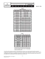
Страница 14: ... 48 Table 3 Crankcase Heater Model Number Kit Number ZB10 ZB14 N A ZB15 ZB29 998 7026 00 ZB30 ZB57 998 7024 00 Table 3A Conduit Ready Heater Terminal Box Kits Table 4 Discharge Thermostat Line Kits Kit Number Conduit Lead Connector Alarm Contact Discharge Line Diameter 998 0540 00 No No 1 2 998 0548 00 No Yes 1 2 998 7022 02 Yes No 1 2 998 7022 04 Yes No 5 8 998 7022 07 ZB48 ZF25 only Yes No 3 4 T...

Страница 15: ... Emerson product remains solely with the purchaser or end user Table 7 Recommended Oil Charges by Model Family Note Theoillevelofrefrigerationscrollcompressors shouldbeadjustedtothemid pointofthesightglass during normal operation Model Family Initial Recharge ZB10KCE 25 22 ZB11 13 14KCE 25 21 ZB15KC E 44 40 ZB19 21 26 29KC E 49 45 ZB30KC E 64 60 ZB38KC E 64 60 ZB45KC E 64 60 ZB48KCE 60 56 ZB57KCE ...

Отзывы: