© 2017 Emerson Climate Technologies, Inc.
7
AE21-1355 R4
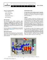
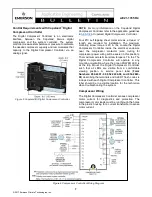
Figure 5 Copeland(R) Digital Compressor Controller
Control Requirements with Copeland
™
Digital
Compressor Controller
The Digital Compressor Controller is an electronics
interface between the Copeland
Discus
digital
compressor and the system controller. The system
controller measures temperature or pressure to calculate
the needed compressor capacity and communicates that
capacity to the Digital Compressor Controller via an
analog signal.
NOTE:
For more information on the Copeland Digital
Compressor Controller refer to the application guidelines
in
Copeland Digital Compressor Controller
.
Four #10 self tapping sheet metal screws, at least ½”
length, are required for installation. The maximum
mounting screw torque is 20 in. lbs. Locate the Digital
Compressor Controller inside the electrical enclosure
near the compressor contactor (wire routing for
compressor power wiring will be easier in this position).
The maximum wire terminal screw torque is 7 in. lbs. The
Digital Compressor Controller will operate in any
mounting orientation where the green POWER LED is
at the top. Mount the Digital Compressor Controller
such that all LEDs are visible from a comfortable
viewing position. A service panel label (
Form
Numbers: 052-2401- 00, 052-2402-00, and 052-2843-
00
) describing the terminals and ALERT flash codes is
included with each Digital Compressor Controller. This
label should be in a visible location for the technician
when troubleshooting the system.
Compressor Wiring
The Digital Compressor Controller senses compressor
motor current for diagnostics and protection. The
compressor motor leads must be run through the holes
in the plastic housing for a current transformer to sense
motor current.
Figure 6 Compressor Controller Wiring Diagram

