background image

12


U.L. Model No.: CF755

The outlet box and joist must be securely mounted and 

capable of supporting at least 50 lbs. Use only a U.L. 

outlet box listed as “Acceptable for Fan Support of 

22.7 kg. (50 lbs.) or less”.


WARNING

!

To reduce the risk of fire, electric shock, or personal 

injury, mount fan to outlet box marked “Acceptable 

for Fan Support of 22.7 kg. (50 lbs.) or less”, and 

use screws supplied with outlet box. Most outlet 

boxes commonly used for support of light fixtures 

are not acceptable for fan support and may need to be 

replaced. Consult a qualified electrician if in doubt.


WARNING

!

4.1

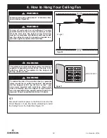
Disconnect electrical power to the Branch Circuit at the 

Circuit Breaker or Fuse Box before attempting to install 

the Ceiling Fan on the Outlet Box (Figure 17).

MAIN FUSE BOX

Figure 17

FLOOR

CEILING

AT LEAST

7'

  Figure 16

4. How to Hang Your Ceiling Fan

The fan must be hung with at least 7’ of clearance from 

floor to blades (Figure 16).


WARNING

!

Turning off wall switch is not sufficient. To avoid 

possible electrical shock, be sure electricity is turned 

off at the main fuse box before wiring. All wiring 

must be in accordance with National and Local codes 

and the ceiling fan must be properly grounded as a 

precaution against possible electrical shock.


WARNING

!

Содержание CF755ORB06

Страница 1: ... Owner s Manual READ AND SAVE THESE INSTRUCTIONS DESIGNER CF755GRT06 Graphite CF755ORB06 Oil Rubbed Bronze CF755WW06 Appliance White Model Numbers www emersonfans com Questions problems missing parts Before returning to the store call Emerson Electric Customer Service 8 a m 6 p m Eastern Monday Friday 1 800 654 3545 Net Weight 18 0 Lbs ...

Страница 2: ...ades 6 Follow the recommended instructions for the proper method of wiring your ceiling fan If you do not know enough about electrical wiring have your fan installed by a licensed electrician NOTE This fan is suitable for use with solid state speed controls NOTE All set screws must be checked and re tightened where necessary before installation 1 Read your owner s manual carefully and keep it for ...

Страница 3: ...er to keep them from being lost If any parts are missing contact your local retailer or catalog outlet for replacement before proceeding H G F E D C B A PACKAGE CONTENTS 11 1 2 3 4 5 6 7 8 9 10 1 2 Remove the Fan Motor Assembly from the protective plastic bag Place all carton contents on a protective surface Place the Fan Motor Assembly into the upper styrofoam with the top of the Motor facing up ...

Страница 4: ...sult a qualified electrician if in doubt WARNING Turning off wall switch is not sufficient To avoid possible electrical shock be sure electricity is turned off at the main fuse box before wiring All wiring must be in accordance with National and Local codes and the ceiling fan must be properly grounded as a precaution against possible electrical shock WARNING To avoid fire or shock follow all wiri...

Страница 5: ...Hanger Ball until the Ball falls freely down the Downrod Figure 1 Remove the Pin from the 3 5 Downrod then remove the Hanger Ball Figure 1 Retain the Pin and Hanger Ball for reinstallation in Step 3 8 Note Do not loosen the Screw that attaches the Green Ground Wire to the Hanger Ball 3 5 DOWNROD THREE 80 MOTOR LEADS UNTWISTED Figure 2 3 2 Separate untwist and unkink the Three 80 Motor Wires Route ...

Страница 6: ...ugh the holes in the Motor Coupler It is critical that the Clevis Pin in the Motor Coupler is properly installed and securely tightened 3 5 DOWNROD MOTOR COUPLER RETIGHTEN UPPER PHILLIPS HEAD SET SCREWS 2 Figure 5 3 5 While pulling up on the Downrod retighten the Two Upper Phillips Head Set Screws to secure the Downrod in the Motor Coupler Figure 5 NOTE The Set Screws must be properly installed as...

Страница 7: ...p of the Hanger Ball Figure 8 Pull the Hanger Ball up tight against the Pin and securely retighten the Phillips Head Set Screw in the Hanger Ball Figure 8 A loose Phillips Head Set Screw could create fan wobble 3 5 DOWNROD GROMMET COUPLER COVER MOTOR HOUSING Figure 6 3 6 Make sure the Grommet is properly installed in the Coupler Cover then slide the Coupler Cover on the Downrod until it rests on t...

Страница 8: ...e Spacer Attachment Screws from the Motor Hub before installation of Blade Assemblies Figure 10 Discard the Spacers and Spacer Screws 3 Ceiling Fan Assembly Continued HANGER BALL 6 to 9 INCHES 1 2 INCH 3 9 The Fan comes with Blue Black and White Wires that are 80 long Measure up approximately 6 to 9 inches above top of Hanger Ball 3 5 Downrod Assembly Figure 9 Cut off excess Wires and strip back I...

Страница 9: ...NECTOR Figure 11 3 12 Remove the three Switch Housing Mounting Screws Figure 12 from the Switch Housing Plate Retain the Screws for future use in Step 3 13 NOTE If you are using an Emerson light fixture with your fan Remove the screw plug from the bottom of the switch housing cover and install the light in accordance with the light kit Owner s Manual Make light kit electrical connections to blue a...

Страница 10: ...e the Switch Housing Assembly by reinstalling the Three Mounting Screws previously removed Figure 13 You have now completed the assembly of your new Ceiling Fan You can now proceed with hanging and wiring your Fan SWITCH HOUSING ASSEMBLY REINSTALL MOUNTING SCREWS 3 Figure 13 Do not pinch wires between the switch housing assembly and the switch housing plate WARNING 10 U L Model No CF755 ...

Страница 11: ...hten the flange screws If one of the flanges does not seat properly on the motor hub loosen the adjacent flange screws re engage and reseat the flanges then tighten the screws again A spare M6 x 14 mm Captive Screw with Lockwasher is supplied in parts bag if needed 3 14 Mount the Blade Flange to the Fan Blade using Three M5 x 6 mm Washer Head Screws and three Blade Washers supplied Figure 14 Repea...

Страница 12: ...replaced Consult a qualified electrician if in doubt WARNING 4 1 Disconnect electrical power to the Branch Circuit at the Circuit Breaker or Fuse Box before attempting to install the Ceiling Fan on the Outlet Box Figure 17 MAIN FUSE BOX Figure 17 FLOOR CEILING AT LEAST 7 Figure 16 4 How to Hang Your Ceiling Fan The fan must be hung with at least 7 of clearance from floor to blades Figure 16 WARNIN...

Страница 13: ... the Outlet Box using the Two Screws supplied with the Outlet Box Figure 18 TWO SCREWS SUPPLIED WITH OUTLET BOX HANGER BRACKET ANTI ROTATION TAB OUTLET BOX Figure 18 4 3 Carefully lift the Fan and seat the Hanger Ball Downrod Assembly on the Hanger Bracket that was just attached to the Outlet Box Figure 19 Be sure the Groove in the Ball is engaged with the Anti Rotation Tab on the Hanger Bracket F...

Страница 14: ...urned off at the main fuse box before wiring NOTE If you are not sure if the outlet box is grounded contact a licensed electrician for advice as it must be grounded for safe operation WARNING This product is designed to use only those parts supplied with this product and or any accessories designated specifically for use with this product by Emerson Electric Co Substitution of parts or accessories...

Страница 15: ...ied Figure 22 BLACK BLUE WIRES WHITE WIRES GREEN WIRES Figure 23 5 4 After connections have been made turn Wires upward and carefully push Wires into the Outlet Box with the White and Green Wires on one side of the Outlet Box and position the Black and Blue Wires on the other side of the Outlet Box Figure 23 Check to see that all connections are tight including ground and that no bare wire is visi...

Страница 16: ...to the Threaded Studs and turn until Studs protrude through the Holes in the Ceiling Cover Figure 25 6 3 Secure the Ceiling Cover in place by sliding Lockwashers over the Threaded Studs and installing the Two Knurled Knobs supplied Figure 25 Tighten the Knurled Knobs securely until the Ceiling Cover fits snugly against the Ceiling and the Hole in the Ceiling Cover is clear of the Downrod 6 1 Screw...

Страница 17: ...position and turn the Ceiling Fan on again Figure 26 The Fan Blades will turn in the opposite direction and reverse the airflow 7 Using Your Ceiling Fan REVERSE SWITCH SWITCH HOUSING ASSEMBLY 7 2 Cut the 3 Speed Switch Pull Chain to a desired length optional Connect the Wood Pendant supplied to the 3 Speed Switch Pull Chain by sliding the Wooden Pendant small hole first onto the Pull Chain Figure ...

Страница 18: ...sories Using the Ceiling Fan Year Round In the summer use the ceiling fan in the counter clockwise direction The airflow produced by the ceiling fan creates a wind chill effect making you feel cooler Select a fan speed that provides a comfortable breeze lower speeds consume less energy In the winter reverse the motor and operate the ceiling fan at low speed in the clockwise direction This produces...

Страница 19: ...ld be avoided to prevent damage to finish 9 Maintenance This product is designed to use only those parts supplied with this product and or any accessories designated specifically for use with this product by Emerson Electric Co Substitution of parts or accessories not designated for use with this product by Emerson Electric Co could result in personal injury or property damage WARNING See your loc...

Страница 20: ...20 U L Model No CF755 11 Repair Parts 16 5 1 2 3 21 17 18 19 13 14 PARTS BAG 11 12 15 4 20 12 11 9 8 6 7 6 7 9 8 5 13 14 10 10 ...

Страница 21: ...CF755ORB06 CF755WW06 Hanger Ball Assembly Consisting of 761655 102 761655 32 761655 1 Hanger Bracket 2 Hanger Ball 3 Downrod Parts Bag Containing 762997 GRT 762997 1 762997 4 Wire Connector 3 5 Threaded Stud 2 6 Lockwasher 2 7 Knurled Knob 2 8 Pin Clevis 1 9 Clip Hairpin 1 10 Screw M6 x 14 mm 1 11 Screw M5 x 6 mm 16 12 Blade Washer 16 13 Wood Pendant 1 14 Coupler 1 15 Blade Balance Kit 1 16 Cover ...

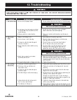
Страница 22: ...t rattling against each other or against the interior wall of the switch housing 5 Motor noise caused by solid state 5 Some fan motors are sensitive to signals from variable speed control Solid State variable speed controls If Solid State Control is used and motor noise results choose an alternative control method 6 Screws holding blades to flanges are loose 6 Tighten screws securely 3 Fan wobbles...

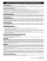
Страница 23: ...cessory caused by normal wear and tear rather than due to defects in materials or workmanship Loss or damage resulting from conditions beyond our reasonable control including without limitation unforeseeable operating environmental conditions repairs not made at Our factory or authorized service center use of parts or accessories not provided to You as part of this warranty by Our factory or autho...

Страница 24: ...his manual for future use Air Comfort Products DIVISION OF EMERSON ELECTRIC CO 8100 W Florissant St Louis MO 63136 Part No F40BP73170004 Form No BP7317 4 Revision 190227 U L Model No CF755 Printed in China 02 19 DATE CODE The date code of this fan may be found on the box stamped in ink on a white label You should record this data above and keep it in a safe place for future use ...

Страница 25: ...lectrodoméstico Números de modelo 1 800 654 3545 www emersonfans com Français page 49 English page 1 No de pieza F40BP73170004 No de formulario BP7317 4 Revisión 190227 No de modelo U L CF755 Preguntas problemas piezas faltantes Antes de devolver el producto a la tienda llame al Servicio al Cliente de Emerson Electric 8 a m a 6 p m Hora del Este lunes a viernes Peso neto 18 0 lb ...

Страница 26: ...a el método apropiado de cablear su ventilador de techo Si no sabe lo suficiente sobre cableado eléctrico haga que un electricista con licencia instale su ventilador NOTA Este ventilador es adecuado para utilizarse con controles de velocidad de estado sólido NOTA Todos los tornillos de ajuste se deben revisar y reapretar donde sea necesario antes de realizar la instalación 1 Lea detenidamente el m...

Страница 27: ...oporte para el ventilador durante las primeras etapas de ensamblaje CONTENIDO DE HERRAJES No instale ni utilice el ventilador si alguna pieza está dañada o falta Llame gratis 1 800 654 3545 ADVERTENCIA Este producto está diseñado para utilizar únicamente las piezas suministradas con este producto y o los accesorios diseñados específicamente por Emerson Electric Co para utilizarse con este producto...

Страница 28: ...en la caja de fusibles principal en este momento y retire el accesorio de iluminación existente Sírvase llamar a asistencia técnica de Emerson al 1 800 654 3545 si tiene alguna pregunta sobre la instalación y utilización de este ventilador de techo ADVERTENCIA Para reducir el riesgo de incendio descargas eléctricas o lesiones corporales monte el ventilador en una caja de tomacorriente marcada con ...

Страница 29: ...el pasador de la varilla descendente de 3 5 pulgadas y luego retire la esfera de suspensión Figura 1 Retenga el pasador y la esfera de suspensión para su reinsta lación en el Paso 3 8 NOTA No afloje el tornillo que sujeta el cable verde de conexión a tierra a la esfera de suspensión VARILLA DESCENDENTE DE 3 5 PULG TRES CABLES DE CONEXIÓN DEL MOTOR DE 80 PULGADAS NO TRENZADOS Figura 2 3 2 Separe de...

Страница 30: ...s crucial que el pasador de horquilla ubicado en el acoplador del motor esté instalado correctamente y apretado firmemente VARILLA DESCENDENTE DE 3 5 PULG REAPRIETE LOS TORNILLOS DE AJUSTE DE CABEZA PHILLIPS SUPERIORES 2 ACOPLAMIENTO DEL MOTOR Figura 5 3 5 Mientras jala hacia arriba la varilla descendente reapriete los dos tornillos de ajuste de cabeza Phillips superiores para fijar la varilla des...

Страница 31: ...ta que quede bien ajustada contra el pasador y reapriete firmemente los dos tornillos de ajuste de cabeza Phillips en la esfera de suspensión Figura 8 Un tornillo de ajuste flojo podría causar oscilación del ventilador VARILLA DESCENDENTE DE 3 5 PULG ARO DE REFUERZO CUBIERTA DEL ACOPLADOR CARCASA DEL MOTOR Figura 6 3 6 Asegúrese de que el aro de refuerzo esté instalado apropiada mente sobre la cub...

Страница 32: ...alar los ensamblajes de paleta Figura 10 Deseche los espaciadores y los tornillos de los espaciadores 6 a 9 PULG 1 2 PULG ESFERA DE SUSPENSIÓN 3 9 El ventilador viene con cables de conexión de color azul negro y blanco que tienen 80 pulgadas de longitud Mida hacia arriba aproximadamente de 6 a 9 pulgadas por encima de la parte superior del ensamblaje de esfera de suspensión varilla descendente de ...

Страница 33: ...ra 12 del plato de la carcasa del interruptor Retenga los tornillos para uso futuro en el Paso 3 13 NOTA Si está usando un accesorio de iluminación Emerson con su ventilador retire el tapón roscado de la parte inferior de la cubierta de la carcasa del interruptor e instale la luz de acuerdo con el manual del usuario del kit de luz Haga las conexiones eléctricas del kit de luz a los cables de conex...

Страница 34: ...carcasa del interruptor reinsta lando los tres tornillos de montaje retirados previa mente Figura 13 ENSAMBLAJE DE LA CARCASA DEL INTERRUPTOR REINSTALE LOS TORNILLOS DE MONTAJE 3 Figura 13 34 3 Ensamblaje del ventilador de techo continuación ADVERTENCIA No aplaste los cables entre el ensamblaje de la carcasa del interruptor y el plato de la cubierta de la carcasa Ahora usted ha completado el ensam...

Страница 35: ...je los tornillos para pestaña adyacentes reacople y reasiente las pestañas y luego apriete de nuevo los tornillos En la bolsa de piezas se suministra un tornillo cautivo M6 x 14 mm con arandela de seguridad de repuesto por si se necesita 3 14 Monte la pestaña para paleta en la paleta del ventilador utilizando tres tornillos con cabeza de arandela M5 x 6 mm y tres arandelas para paleta suministrada...

Страница 36: ...propiadamente a tierra como precaución contra posibles descargas eléctricas ADVERTENCIA La caja de tomacorriente y la viga deben estar montadas de manera segura y ser capaces de soportar por lo menos 50 lbs Utilice únicamente una caja de tomacorriente U L listada con las palabras Acceptable for Fan Support of 22 7 kg 50 lbs or less Aceptable para soportar ventiladores de 22 7 kg 50 lbs o menos ADV...

Страница 37: ...ra esté alineada con la lengüeta antirrotación ubicada en el soporte de suspensión Figura 19 LENGÜETA ANTIRROTACIÓN NOTA LA CUBIERTA DEL TECHO LOS CABLES DE ALIMENTACIÓN Y LOS CABLES DEL VENTILADOR SE HAN OMITIDO PARA OFRECER MAYOR CLARIDAD CAJA DE TOMACORRIENTE ENSAMBLAJE DE ESFERA DE SUSPENSIÓN VARILLA DESCENDENTE SOPORTE DE SUSPENSIÓN SOPORTE DE SUSPENSIÓN ESFERA DE SUSPENSIÓN RANURA DE LA ESFE...

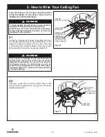
Страница 38: ...TRO DEL CONDUCTOR DE CONEXIÓN A TIERRA CONECTOR DE CABLES LISTADO CABLE VERDE DE CONEXIÓN A TIERRA PROCEDENTE DE LA ESFERA DE SUSPENSIÓN CABLE VERDE DE CONEXIÓN A TIERRA PROCEDENTE DEL SOPORTE DE SUSPENSIÓN Figura 20 5 Cómo cablear su ventilador de techo ADVERTENCIA Para evitar posibles descargas eléctricas asegúrese de que la electricidad esté desconectada en la caja de fusibles principal antes d...

Страница 39: ...BLES DE COLOR NEGRO Y DE COLOR AZUL CABLES VERDES Figura 23 5 4 Después de que se hayan hecho las conexiones gire los cables de conexión hacia arriba y empújelos cuidadosamente hacia el interior de la caja de tomacorriente con los cables de conexión verde y blanco en un lado de la caja de tomacorriente y los cables de conexión negro y azul en el otro lado de dicha caja Figura 23 5 Cómo cablear su ...

Страница 40: ...nstalando los dos pomos estriados suministrados Figura 25 Apriete de manera segura los pomos estriados hasta que la cubierta del techo quede bien ajustada contra el techo y la varilla descendente no toque el agujero ubicado en la cubierta del techo 6 1 Enrosque los dos espárragos roscados suministrados en los agujeros roscados del soporte de suspensión Figura 24 ESPÁRRAGOS ROSCADOS 2 Figura 24 6 E...

Страница 41: ...el ventilador y espere a que las paletas dejen de girar Deslice el interruptor de inversión ubicado en la parte superior del ensamblaje de la carcasa del interruptor hasta la posición opuesta y encienda de nuevo el ventilador de techo Figura 26 Las paletas girarán en sentido contrario e invertirán la circulación de aire 7 Utilización de su ventilador de techo Información sobre el interruptor de in...

Страница 42: ...contrario al de las agujas del reloj La circulación de aire producida por el ventilador crea un efecto de viento frío que hace que usted se sienta más fresco Seleccione una velocidad del ventilador que proporcione una brisa agradable Las velocidades más bajas consumen menos energía En invierno invierta el sentido de giro del motor y utilice el ventilador de techo a baja velocidad de manera que gir...

Страница 43: ...sorios Kits de luces del ventilador de techo Controles del ventilador de techo y la luz Kits de extensión de varilla descendente 10 Accesorios ADVERTENCIA No use agua cuando limpie su ventilador de techo El agua podría dañar el motor o las paletas y crear la posibilidad de una descarga eléctrica ADVERTENCIA El uso de cualquier otro control que no esté aprobado específica mente para este ventilador...

Страница 44: ...44 No de modelo U L CF755 16 5 1 2 3 21 17 18 19 13 14 PARTS BAG 11 12 15 4 20 12 11 9 8 6 7 6 7 9 8 5 13 14 10 10 11 Piezas de repuesto BOLSA DE PIEZAS ...

Страница 45: ...ante de madera 1 14 Acoplador 1 15 Kit de equilibrado 1 16 Cubierta del techo 1 761620 GRT 761620 33 761620 17 Cubierta del acoplador 1 762463 GRT 762463 16 762463 15 18 Arnés de cableado 762993 1 762993 1 762993 3 19 Carcasa del interruptor 763151 GRT 763151 ORB 763151 WW 20 Conjunto de paletas conjunto de 5 761859 CR AC 761859 29 761859 3 21 Conjunto de pestañas conjunto de 5 763154 GRT 763154 O...

Страница 46: ... de estado sólido y se produce ruido del motor escoja un método de control alternativo 6 Los tornillos que sujetan las paletas a las pestañas están flojos 6 Apriete firmemente los tornillos 3 El ventilador oscila excesivamente 1 El tornillo de ajuste del acoplador del motor está flojo 1 Apriete firmemente ambos tornillos de ajuste en el acoplador del motor 2 El tornillo del ensamblaje de esfera de...

Страница 47: ...ucto de Ventilador de Techo Emerson por causa del desgaste por el uso normal en lugar de por causa de defectos de materiales o de fabricación Pérdida o daño que resulte de situaciones que estén más allá de nuestro control razonable incluyendo sin limitación condiciones ambientales operativas imprevisibles reparaciones no realizadas en Nuestro centro de servicio de fábrica o de servicio autorizado ...

Страница 48: ... producto a la tienda llame al Servicio al Cliente de Emerson Electric 8 a m a 6 p m Hora del Este lunes a viernes Retenga este manual para uso futuro Impreso en China 02 19 CÓDIGO DE FECHA ________________________________________________________________________________________ El código de fecha de este ventilador se puede encontrar en la caja estampado en tinta en una etiqueta blanca Usted deber...

Страница 49: ...ectroménager Numéros des modèles 1 800 654 3545 www emersonfans com Español página 25 English page 1 Pièce N F40BP73170004 Formulaire N BP7317 4 Révision 190227 Modèle U L N CF755 Questions problèmes pièces manquantes Avant de retourner un produit au magasin veuillez téléphoner au Emerson Electric Customer Service 8h00 18h00 HNE du lundi au vendredi Poids net 18 0 lbs ...

Страница 50: ...uez du nettoyage ou de la peinture ou lorsque vous travaillez à proximité Mettez toujours le ventilateur de plafond hors tension avant d effectuer une quelconque opération d entretien ou de maintenance 3 N insérez rien entre les pales du ventilateur pendant qu elles sont en train de tourner 4 Ne mettez pas le ventilateur en marche arrière avant que les pales du ventilateur ne se soient complètemen...

Страница 51: ...yrène du haut sert de conteneur pour le ventilateur pendant les premiers stades du montage AVERTISSEMENT Ce produit est conçu pour n être utilisé qu avec les pièces fournies avec celui ci et ou les accessoires conçus spécifiquement pour emploi avec ce produit par Emerson Electric Co Toute substitution de pièces ou d accessoires non conçus pour emploi avec ce produit par Emerson Electric Co risquer...

Страница 52: ...z l alimentation électrique du coffret à fusibles principal et retirez le luminaire existant Veuillez contacter le support technique d Emerson au 1 800 654 3545 si vous avez des questions concernant l installation et le fonction nement de ce ventilateur de plafond AVERTISSEMENT Pour réduire le risque d incendie de choc électrique ou de blessure montez le ventilateur sur le boîtier de prises de cou...

Страница 53: ...uspension descendante Figure 1 Retirez l axe de la tige de suspension descendante de 3 5 po puis retirez la rotule de la tige de sus pension Figure 1 Conservez l axe et la rotule de la tige de suspension en vue de leur réinstallation lors de l Étape 3 8 Remarque Ne desserrez pas la vis qui attache le fil de mise à la terre vert TIGE DE SUSPENSION DESCENDANTE DE 3 5 po TROIS CÂBLES DE MOTEUR DE 80 ...

Страница 54: ...eur Il est crucial que l axe à épaulement dans le dispositif de couplage du moteur soit installé correctement et serré à fond TIGE DE SUSPENSION DESCENDANTE DE 3 5 po RESSERREZ LES 2 VIS DE RÉGLAGE À TÊTE CRUCIFORME DU HAUT COUPLEUR DU MOTEUR Figure 5 3 5 Tout en tirant la tige de suspension descendante vers le haut resserrez les deux vis de réglage à tête cruciforme du haut afin de sécuriser la t...

Страница 55: ...nter jusqu à ce qu elle soit serrée contre l axe et assujettissez solidement la vis de pression à tête cruciforme dans la rotule Figure 8 Le ventilateur risquerait de trembler si la vis de pression à tête cruciforme n était pas serrée suffisamment TIGE DE SUSPENSION DESCENDANTE DE 3 5 po ŒILLET CACHE DU COUPLEUR BOÎTIER DU MOTEUR Figure 6 3 6 Assurez vous que l œillet est installé correctement dan...

Страница 56: ...es du moyeu du moteur avant de procéder à l installation des ensembles de pales Figure 10 Jetez les cales temporaires et les vis de fixation des cales DE 6 À 9 po DE 15 À 23 cm 1 2 po 1 27 cm ROTULE DE LA TIGE DE SUSPENSION 3 9 Le ventilateur est fourni avec des fils bleu noir et blanc mesurant 80 po de long Mesurez approximativement de 6 à 9 po de 15 à 23 cm en dessus du haut de l ensemble de tig...

Страница 57: ...gure 12 de la plaque du boîtier de l interrupteur Mettez les vis de côté pour pouvoir vous en servir à nouveau ultérieurement à l étape 3 13 REMARQUE Si vous utilisez un luminaire Emerson avec votre ventilateur retirez la fiche de vissage du fond du cache du boîtier de l interrupteur et installez le luminaire conformément au Mode d emploi du luminaire Effectuez les raccordements électriques du lum...

Страница 58: ...réinstallant les trois vis de montage qui avaient été retirées précédemment Figure 13 ENSEMBLE DE BOÎTIER DE L INTERRUPTEUR RÉINSTALLEZ LES 3 VIS DE MONTAGE Figure 13 58 3 Assemblage du ventilateur de plafond suite AVERTISSEMENT N écrasez pas les fils entre l ensemble du kit de luminaire et l adaptateur du kit de luminaire Vous avez à présent achevé le montage de votre nouveau ventilateur de plafo...

Страница 59: ...ride de fixation adjacente réengagez les brides de fixation puis assurez vous qu elles reposent bien à leur place et serrez alors à nouveau les vis Une vis captive M6 x 14 mm avec une rondelle de blocage est fournie dans le sac des pièces de rechange pour le cas où elle serait nécessaire 3 14 Montez la bride de fixation de la pale sur la pale du ventilateur à l aide de trois vis à tête à embase M5...

Страница 60: ...à la terre à titre de précaution pour assurer la protection contre les risques de choc électrique AVERTISSEMENT Le boîtier de prises de courant et la solive doivent être installés de façon sécurisée et être capables de supporter sans problème au moins 50 livres 22 7 kg Utilisez seulement des boîtiers de prises de courant homologués U L comportant l indication suivante Acceptable for Fan Support of...

Страница 61: ...nure de la rotule est alignée sur la languette antirotation du support de suspension Figure 19 LANGUETTE ANTIROTATION REMARQUE CACHE POUR PLAFOND CÂBLES D ALIMENTATION ET CÂBLES DU VENTILATEUR NON INDIQUÉS À DESSIN DANS UN BUT DE CLARTÉ BOÎTIER DE PRISES DE COURANT SUPPORT DE SUSPENSION SUPPORT DE SUSPENSION ROTULE DE LA TIGE RAINURE DE LA ROTULE DE LA TIGE DE SUSPENSION ENSEMBLE DE TIGE DE SUSPEN...

Страница 62: ... éviter tout risque de choc électrique assurez vous que l ali mentation électrique est coupée au niveau du boîtier des fusibles avant d effectuer le câblage REMARQUE Si vous ne pouvez pas affirmer avec certitude que le boîtier de prises de courant est mis à la terre contactez un élec tricien agréé pour obtenir des conseils car le boîtier doit absolu ment être relié à la terre pour garantir une séc...

Страница 63: ...S NOIR ET BLEU FILS VERTS Figure 23 5 4 Après avoir réalisé les connexions orientez les fils vers le haut et enfoncez délicatement les fils dans le boîtier de prises de courant avec les fils blanc et vert d un côté du boîtier de prises de courant et les fils noir et bleu de l autre côté du boîtier de prises de courant Figure 23 AVERTISSEMENT Vérifiez que tous les raccordements sont bien serrés y c...

Страница 64: ...ons moletés fournis Figure 25 Serrez autant que possible les boutons moletés jusqu à ce que la cache pour plafond soit ajustée au ras du plafond et jusqu à ce que le trou dans la cache pour plafond ne soit plus en contact avec la tige de suspension descendante 6 1 Vissez les deux goujons filetés fournis dans les trous taraudés du support de suspension Figure 24 GOUJONS FILETÉS 2 Figure 24 6 Assemb...

Страница 65: ...ommutateur d inversion situé sur le côté de l ensemble de moteur du ventilateur dans le sens contraire et remettez ensuite le ventilateur de plafond en marche Figure 26 Les pales du ventilateur tourneront dans l autre sens et l air circulera dans la direction opposée 7 Utilisation de votre ventilateur de plafond Informations sur le commutateur d inversion du sens de fonctionnement Saison Sens de r...

Страница 66: ...d air du ventilateur de plafond crée un effet de refroidissement et vous procure une sensation de fraîcheur Sélectionnez la vitesse qui vous convient pour générer une brise agréable en gardant à l esprit qu en réduisant la vitesse vous consommerez moins d énergie Pendant l hiver inversez le sens de rotation et faites fonctionner le ventilateur de plafond à une vitesse réduite dans le sens des aigu...

Страница 67: ...oires Kits de luminaires de ventilateur de plafond Commandes du ventilateur de plafond et du luminaire Kits d extension pour tige de suspension descendante 10 Accessoires AVERTISSEMENT N utilisez pas d eau lorsque vous nettoyez votre ventilateur de plafond car ceci pourrait endommager le moteur ou les pales et vous exposer à un risque de choc électrique AVERTISSEMENT L utilisation de toute autre c...

Страница 68: ...68 Modèle UL N CF755 16 5 1 2 3 21 17 18 19 13 14 PARTS BAG 11 12 15 4 20 12 11 9 8 6 7 6 7 9 8 5 13 14 10 10 11 Pièces de rechange SAC DE PIÈCES ...

Страница 69: ...age de pales 1 16 Cache pour plafond 761620 GRT 761620 33 761620 17 Cache du coupleur 762463 GRT 762463 16 762463 15 18 Faisceau de cables 762993 1 762993 1 762993 3 19 Boîtier d interrupteur 763151 GRT 763151 ORB 763151 WW 20 Ensemble de pales jeu de 5 761859 CR AC 761859 29 761859 3 21 Ensemble de brides de fixation jeu de 5 763154 GRT 763154 ORB 763154 WW Mode d emploi BP7317 4 BP7317 4 BP7317 ...

Страница 70: ...si cela a pour effet que le moteur est bruyant choisissez une autre méthode de commande 6 Il se peut que les vis servant à raccorder les pales aux brides soient mal serrées 6 Serrez les vis au maximum 3 Le ventilateur tremble de manière excessive 1 Les vis attachant les pales du ventilateur au moteur ne sont pas suffisamment serrées 1 Soulevez le cache du coupleur et serrez la vis de pression auta...

Страница 71: ...eur de plafond Emerson ou un accessoire d un Ventilateur ou Produit pour un ventilateur de plafond Emerson causés par l usure normale plutôt que par des défauts de fabrication ou de matériel Les pertes et dommages résultant de conditions au delà de notre contrôle raisonnable y compris sans toutefois s y limiter les conditions environnementales de fonctionnement imprévisibles les réparations n ayan...

Страница 72: ... veuillez téléphoner au Service à la clientèle d Emerson Electric 8h00 18h00 HNE du lundi au vendredi Conservez ce mode d emploi pour toute utilisation future Imprimé en Chine 02 19 CODE DE DATE _____________________________________________________________________________________________ Le code de date de ce ventilateur est placé sur la boîte estampé à l encre sur une étiquette blanche Il faut en...

Отзывы: