Emerson Bettis G01XXXX-M11 series Скачать руководство пользователя страница 46

Service Instructions

124843E Rev. C


August 2015

42

Section 9: Document Revision

Document Revision

Section 9: Document Revision

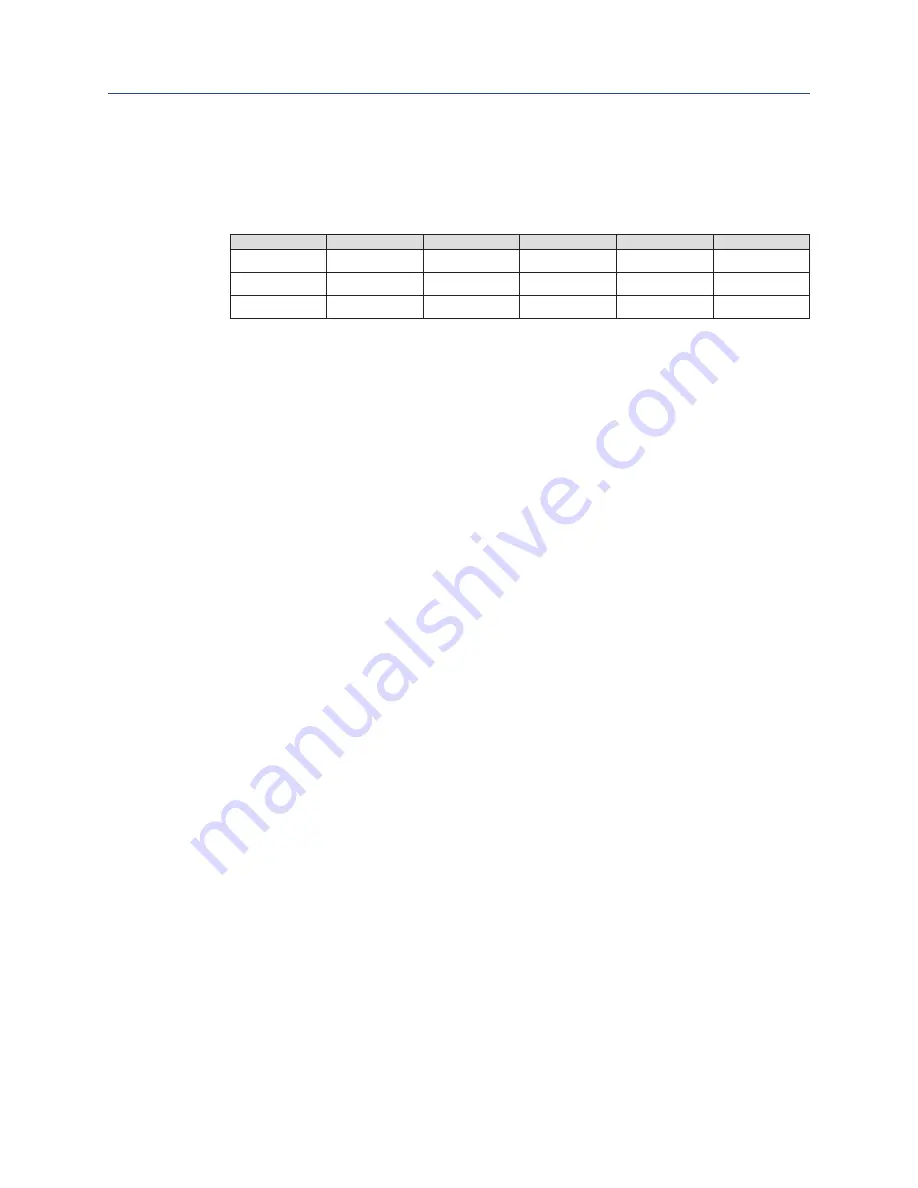
Table 17� 

Revision Overview

ECN

DATE

REV

BY *

DATE

Released

Jan. 2002

A

B.Cornelius

Jan. 2002

19110

July 2006

B

UPDATED

C. Ross

July 2006

VAWCO2750

Aug. 2015

C

UPDATED

C. Rico

Aug. 2015

* Signatures on file Bettis, Houston, Texas

Содержание Bettis G01XXXX-M11 series

Страница 1: ...Service Instructions 124843E Rev C August 2015 G01 through G10 Double Acting Pneumatic Actuators with M11 Hydraulic Override ...

Страница 2: ......

Страница 3: ...assembly 6 2 3 Drive Module Disassembly 9 2 4 M11 Hydraulic Override Cylinder Disassembly 11 Section 3 Actuator Reassembly 3 1 General Reassembly 13 3 2 Drive Module Reassembly 13 3 3 Pneumatic Power Module Reassembly 18 3 4 G2 and G3 Early Model Pneumatic Power Module Reassembly 21 3 5 M11 Hydraulic Override Cylinder Reassembly 23 3 6 Actuator Testing 25 Section 4 Field Conversions 4 1 Constructi...

Страница 4: ...l Style and Wrench Size 35 6 5 G3 Tool Style and Wrench Size 35 6 6 G4 Tool Style and Wrench Size 36 6 7 G5 Tool Style and Wrench Size 36 6 8 G7 Tool Style and Wrench Size 37 6 9 G8 Tool Style and Wrench Size 37 6 10 G10 Tool Style and Wrench Size 38 Section 7 Troubleshooting 7 1 Fault Insertion 39 7 2 Operational Test 40 Section 8 Removal and Decommissioning 8 1 Removal and Decommissioning 41 Sec...

Страница 5: ...he module s that are to be worked on 1 1 5 This procedure should only be implemented by a technically competent technician who should take care to observe good workmanship practices 1 1 6 Numbers in parentheses indicate the bubble number reference number used on the Bettis assembly drawing and Actuator Parts List 1 1 7 This procedure is written using the stop screw side of the housing 1 10 as a re...

Страница 6: ...nformation Products supplied by Bettis in its as shipped condition are intrinsically safe if the instructions contained within this Service Instruction are strictly adhered to and executed by well trained equipped prepared and competent personnel WARNING READ WARNING MESSAGES CAREFULLY For the protection of personnel working on Bettis actuators this procedure should be reviewed and implemented for...

Страница 7: ... tools are required only when extension rod assembly 1 50 or 9 50 is removed or when a new extension rod assembly is installed Table 1 G Series Actuator Models Actuator Model Bettis Part Number Actuator Model Bettis Part Number G01 None required G5 G7 117369 G2 123616 G8 G10 117368 G3 G4 117370 1 5 3 Commercial leak testing solution 1 5 4 Non hardening thread sealant 1 6 Lubrication and Fluid Requ...

Страница 8: ...ach type Mountings are designed to be as simple as possible to keep the guess work out of the installation 1 9 2 Actuators that are shipped from the factory with the travel stops adjusted for approximately ninety degree rotation Generally it is necessary to make slight travel stop adjustments once the actuator is installed onto the valve Refer to the valve manufacturer s recommendations for specif...

Страница 9: ...ed by a number of factors includes 1 Power supply line length 2 Power supply line size 3 Power supply line pressure 4 Control valve and fitting orifice size 5 Torque requirements of the valve 6 Size of the actuator 7 Setting of speed controls 8 Hydraulic manual override where available 1 10 5 Due to the interaction of these variables it is difficult to specify a normal operating time Faster operat...

Страница 10: ...mbled separate to the actuator refer to Section 5 Module Removal And Installation NOTE Use a means of capturing the hydraulic fluid that will be lost during the removal or disassembly of the hydraulic override power module Use a bucket tub and large container etc 2 1 3 To ensure correct reassembly that is with pneumatic power module or M11 hydraulic cylinder assembly on same end of drive module as...

Страница 11: ...e wrench to remove tie bars 2 2 6 TIE BAR REMOVAL NOTE G01 G2 and G3 models have flats on outboard end of tie bars 3 20 for wrench placement 2 2 6 1 Remove G01 G2 and G3 tie bars 3 20 as follows 2 2 6 1 1 Unscrew tie bars 3 20 from inner end cap 3 10 Pull the tie bars out of the inner end cap far enough to expose the O ring seals 4 80 2 2 6 1 2 Remove O ring seals 4 80 from the inboard end of tie ...

Страница 12: ...ing halves 3 50 and one retainer ring 3 60 from inboard side of piston 3 30 NOTE Piston 3 30 acts as the retainer for outboard split ring halves 3 50 2 2 8 2 Slide piston 3 30 toward the inner end cap 3 10 until the out board split ring halves is exposed enough for removal Remove outboard split ring halves from piston rod 3 40 2 2 8 3 Remove piston 3 30 and two split ring halves 3 50 from piston r...

Страница 13: ... with step 2 3 5 2 3 4 Remove one vent check assembly 13 from top of housing cover 1 20 2 3 5 Unscrew and remove hex cap screws 1 160 with lockwashers 1 170 from yoke cover 1 150 2 3 6 Remove yoke cover 1 150 from housing cover 1 20 2 3 7 Mark and record the orientation of the position indicator assembly 1 140 in relation to the top of yoke 1 70 2 3 8 Remove position indicator assembly 1 140 from ...

Страница 14: ...10 from inside bottom of housing 1 10 2 3 19 Remove yoke pin 1 80 by inserting 3 8 16 UNC screw into top of the yoke pin and pull straight up and out 2 3 20 Remove guide block 1 30 from between the arms of yoke 1 70 2 3 21 Remove yoke guide block bushing 2 30 from top of guide block 1 30 2 3 22 Remove yoke guide block bushing 2 30 from the top of the lower yoke arm of yoke 1 70 NOTE G01 model actu...

Страница 15: ...OTE Control knob 20 320 is located in front and at the bottom of the M11 pump manifold 20 10 Using a means of capturing the hydraulic fluid that will be lost during the follow ing steps Use a bucket tub and large container etc 2 4 2 Remove all the piping from the M11 override cylinder outer end cap 7 80 and inner end cap 7 10 2 4 3 Mark and record location of the ports on outer end cap 7 80 and in...

Страница 16: ...uts 7 105 from hex cap screws 7 100 2 4 15 Remove hex cap screws 7 100 with lockwashers 7 110 from inner end cap 7 10 and housing 1 10 2 4 16 Remove inner end cap 7 10 off of piston rod 7 40 NOTE The piston rod 7 40 removal as outlined in step 2 4 17 is only required when the piston rod is being replaced or when the drive module is to be disassembled 2 4 17 Remove piston rod 7 40 from the drive mo...

Страница 17: ...hat will be subjected to sliding or rotating motion Sealing surfaces of the cylinder tie bars and piston rod must be free of deep scratches pitting corrosion and blistering or flaking coating CAUTION INSPECT PARTS BEFORE USE Actuator parts that reflect any of the above listed characteristics should be replaced with new parts 3 1 4 Before installation coat all moving parts with a complete film of l...

Страница 18: ...40 over threaded end of extension rod assembly 1 50 NOTE The spherical side of the washer will go on the extension rod assembly facing the head of the extension rod assembly 3 2 5 Install extension rod assembly 1 50 into guide block 1 30 and up against the first spherical washer 1 40 3 2 6 Install extension retainer nut assembly 1 60 over extension rod assembly 1 50 and screw into guide block 1 30...

Страница 19: ...ring into housing cover 1 20 and housing 1 10 NOTE The yoke bearing 2 40 must be pressed into housing 1 10 and housing cover 1 20 Install the yoke bearings with the bearing seam located 45 5 degrees from the yoke arm slot when yoke 1 70 is rotated to its full clockwise position 3 2 15 If the two yoke pin bearings 2 10 are being replaced install new bearing into housing cover 1 20 and housing 1 10 ...

Страница 20: ...r spring pin 1 100 NOTE Refer to Section 2 step 2 3 7 for correct installation position 3 2 25 Install O ring 2 50 into housing cover 1 20 3 2 26 Install O ring seal 2 60 into housing cover 1 20 3 2 27 Install housing cover 1 20 being careful not to damage O ring seals 2 50 and 2 60 3 2 28 Place lockwashers 1 115 onto hex cap screws 1 110 NOTE On G7 through G10 model actuators apply thread adhesiv...

Страница 21: ...2 100 onto position indicator 1 140 3 2 35 Install upper bearing 2 120 into yoke cover 1 150 3 2 36 Install rod wiper 2 80 into yoke cover 1 150 3 2 37 Install O ring seal 2 70 into yoke cover 1 150 3 2 38 Install yoke cover 1 150 onto housing cover 1 20 and over position indicator assembly 1 140 NOTE During yoke cover installation be careful not to damage O ring seal 2 70 and rod wiper 2 80 3 2 3...

Страница 22: ...r piston rod 3 40 3 THE ACTUATOR MUST BE IN THE APPROPRIATE OVERTRAVEL POSITION Confirm over travelpositionbyobservingtheguideblock 1 30 isagainsttheinnerwallofhousing 1 10 3 3 1 Lubricate piston rod 3 40 and insert through the side of housing 1 10 3 3 1 1 G2 through G10 screw piston rod 3 40 onto extension rod assembly 1 50 3 3 1 2 G01 screw piston rod 3 40 onto guide block 1 30 3 3 2 Torque tigh...

Страница 23: ...nstalling the back up rings do not align the skive cuts 3 3 11 4 If the back up rings are too long and the rings overlap beyond the skive cuts then the rings must be trimmed with a razor sharp instrument 3 3 12 Install two split ring halves 3 50 into the inner most groove in piston rod 3 40 and retain by installing the recessed area of piston 3 30 onto the piston rod and over the two split ring ha...

Страница 24: ...tall outer end cap 3 80 over tie bars 3 20 and into cylinder 3 70 NOTE The pressure inlet port should be positioned in the same position as recorded in Section 2 step 2 2 1 3 3 23 Install tie bar nuts 3 90 onto tie bars 3 20 Torque tighten tie bar nuts alternately in 100 foot pound N m increments until a final lubricated torque as listed in the following table has been achieved Table 4 Tie Bar Nut...

Страница 25: ...nto inner end cap 3 10 3 4 3 Coat one Polypak seal 4 30 with lubricant and install lip first into inner end cap 3 10 CAUTION INSTALL POLYPAK SEAL CORRECTLY Install the Polypak seal with energizer ring facing outboard side of inner end cap 3 10 3 4 4 Install piston rod 3 40 through inner end cap 3 10 NOTE The piston rod end with retainer grooves to be on the outboard side of inner end cap 3 10 NOTE...

Страница 26: ...nstalling the recessed area of piston 3 30 over the two split halves 3 50 3 4 10 Install two split ring halves 3 50 into the piston rod in back of the piston and retain with retainer ring 3 60 3 4 11 Coat two tie bars 3 20 with lubricant and install by carefully pushing tie bars through piston 3 30 and rod T seal 4 50 3 4 12 Install two tie bar O ring seals 4 80 onto the inboard end of tie bars 3 ...

Страница 27: ...wer module per Section 5 steps 5 2 3 5 M11 Hydraulic Override Cylinder Reassembly NOTE Review Section 3 1 General Reassembly before proceeding with the M11 hydraulic over ride cylinder reassembly NOTE In Section 3 5 where the step indicates to lubricate coat or apply fluid use hydraulic fluid as identified in Section 1 step 1 6 2 for lubricating the part being installed 3 5 1 Lubricate piston rod ...

Страница 28: ...10 CAUTION INSTALL POLYPAK SEAL CORRECTLY Install the Polypak seal with energizer ring facing piston side of inner end cap 7 10 3 5 13 Install rod bushing 8 20 into inner end cap 7 10 3 5 14 Install rod wiper 8 10 into inner end cap 7 10 3 5 15 Install one O ring seal 8 90 into inboard face of inner end cap 7 10 3 5 16 Install inner end cap 7 10 onto piston rod 7 40 3 5 17 Install two tie bars 7 2...

Страница 29: ... rod 3 40 per the chart in Section 5 4 step 5 4 5 3 5 25 Install the M11 Hydraulic Override Cylinder per Section 5 step 5 4 3 6 Actuator Testing 3 6 1 Leakage Test All areas where leakage to atmosphere may occur are to be checked using a commercial leak testing solution CAUTION DO NOT EXCEED MAXIMUM PRESSURE Pressure applied to the actuator is not to exceed the maximum operating pressure rating li...

Страница 30: ... end cap 3 10 3 6 4 4 Remove pressure from the pressure inlet port 3 6 5 If an actuator was disassembled and repaired the above leakage test must be performed again 3 6 6 Shell Pressure Test Optional pressure test could be performed on PED certified actuator by applying pressure to both sides of the piston simultaneously for a period of two 2 minutes If any leakage occurs across a static seal the ...

Страница 31: ...4 1 1 Remove pneumatic power module per Section 5 1 4 1 2 Remove M11 hydraulic override cylinder per Section 5 3 4 1 3 Using Section 5 1 reinstall the pneumatic power module onto the opposite end of housing 1 10 as it was previously located 4 1 4 Using Section 5 3 reinstall the M11 hydraulic override cylinder onto the opposite end of housing 1 10 as it was previously located ...

Страница 32: ...ng power module from housing 1 10 be careful not to lose O ring seal 4 90 5 1 4 Remove power module from actuator housing 1 10 5 2 Pneumatic Power Module Installation NOTE Reinstall the power module onto the opposite side of housing 1 10 as it was previously located 5 2 1 Check to verify that O ring seal 4 90 is properly seated in its seal groove located on the housing side of inner end cap 3 10 N...

Страница 33: ...3modelactuatorstorqueto90Lbf ft 122N m 5 Percent lubricated 5 2 5 3 G4 through G10 model actuators torque to 240 FT lb 325 N m 5 Percent lubricated 5 2 6 Install lock washers 3 110 onto hex cap screws 3 100 5 2 7 Install and tighten hex cap screws 3 100 with lockwashers through housing 1 10 and into inner end cap 3 10 5 2 8 Using pipe dope install pipe plug 3 120 into outer end cap 3 80 5 3 M11 Hy...

Страница 34: ... guide block threads do not cross thread 5 4 4 G2 THROUGH G10 MODEL ACTUATORS 5 4 4 1 Align piston rod 7 40 with extension rod assembly 9 50 5 4 4 2 Using a male square drive extension go through outer end cap 7 80 and screw piston rod 7 40 into extension rod assembly 9 50 WARNING DO NOT CROSS THREAD PISTON ROD When screwing piston rod into extension rod assembly 9 50 make certain that the piston ...

Страница 35: ...oved and pushing on the guide block 5 5 2 Use Bettis tool part number as listed in chart in Section 1 step 1 2 1 to remove retainer nut assembly X 60 from the guide block 1 30 CAUTION DO NOT DROP SPHERICAL WASHERS When removing rod extension assembly from guide block be careful not to drop one of the spherical washers inside the housing 5 5 3 Remove rod extension assembly X 50 from guide block 1 3...

Страница 36: ...l be facing to the outside of guide block 1 30 5 6 4 Install second spherical washer X 40 over threaded end of extension rod assembly X 50 NOTE The spherical side of the washer will go on the extension rod assembly facing the head of the extension rod assembly 5 6 5 Install extension rod assembly X 50 into right of guide block 1 30 and up against the first spherical washer X 40 5 6 6 Install exten...

Страница 37: ... N A N A 9 Dia Power Kg 30 5 36 N A N A N A N A N A N A 3 Lbs 75 73 5 88 N A N A N A N A N A 10 Dia Power Kg 34 33 40 N A N A N A N A N A 3 Lbs 86 86 104 130 N A N A N A N A 12 Dia Power Kg 39 39 47 59 N A N A N A N A 3 Lbs 96 96 114 145 N A N A N A N A 14 Dia Power Kg 44 44 51 66 N A N A N A N A 3 Lbs N A 135 145 168 295 N A N A N A 16 Dia Power Kg N A 61 66 76 134 N A N A N A 3 Lbs N A N A 235 2...

Страница 38: ... A N A 7 Lbs N A N A N A N A N A N A 485 N A 7 0 Dia H Power Module Kg N A N A N A N A N A N A 220 N A 7 Lbs N A N A N A N A N A N A N A 808 9 0 Dia H Power Module Kg N A N A N A N A N A N A N A 367 7 Lbs 32 32 32 32 35 35 45 50 M11 Pump Reservoir Kg 14 5 14 5 14 5 14 5 15 9 15 9 20 4 22 7 6 3 G01 Tool Style and Wrench Size Table 8 G01 Tool Style and Wrench Size ITEM NO WRENCH SIZE ITEM QTY LOCATI...

Страница 39: ... 9 16 4 Standard Hex Nuts Socket 7 115 9 16 4 Hex Cap Screws Socket 7 120 9 16 Sq 1 NPT Pipe Plug Open End or Adjustable 13 3 4 2 Vent Check Assembly Open End 6 5 G3 Tool Style and Wrench Size Table 10 G3 Tool Style and Wrench Size ITEM NO WRENCH SIZE ITEM QTY LOCATION OR DESCRIPTION RECOMMENDED TOOL STYLE 1 110 9 16 8 Hex Cap Screws Socket 1 160 9 16 4 Hex Cap Screws Socket 1 180 1 2 Sq 2 Stop Sc...

Страница 40: ...ndard Hex Nuts Socket 7 115 3 4 4 Hex Cap Screws Socket 7 120 5 8 Sq 1 NPT Pipe Plug Open End or Adjustable 13 3 4 2 Vent Check Assembly Open End 6 7 G5 Tool Style and Wrench Size Table 12 G5 Tool Style and Wrench Size ITEM NO WRENCH SIZE ITEM QTY LOCATION OR DESCRIPTION RECOMMENDED TOOL STYLE 1 110 3 4 8 Hex Cap Screws Socket 1 120 3 4 4 Hex Cap Screws Socket 1 160 9 16 6 Hex Cap Screws Socket 1 ...

Страница 41: ... 15 16 8 Standard Hex Nuts Socket 7 115 15 16 8 Hex Cap Screws Socket 7 120 15 16 1 NPT Pipe Plug Open End or Adjustable 13 3 4 2 Vent Check Assembly Open End 6 9 G8 Tool Style and Wrench Size Table 14 G8 Tool Style and Wrench Size ITEM NO WRENCH SIZE ITEM QTY LOCATION OR DESCRIPTION RECOMMENDED TOOL STYLE 1 110 3 4 12 Hex Cap Screws Socket 1 120 3 4 4 Hex Cap Screws Socket 1 160 9 16 8 Hex Cap Sc...

Страница 42: ...ket 1 180 1 1 2 2 Stop Screws Open End or Adjustable 3 20 3 4 Sq 2 Tie Bar female square Open End or Adjustable 3 40 3 4 Sq 1 Piston Rod Male Drive 3 90 3 1 2 2 Heavy Hex Nuts Socket 3 100 1 5 16 8 Hex Cap Screws Socket 3 120 1 5 16 Sq 1 Pipe Plug Open End or Adjustable 3 130 3 16 2 Socket Cap Screws Allen 7 40 3 4 Sq 1 Piston Rod Male Drive 7 90 3 1 2 8 Hex Nuts Socket 7 100 1 1 8 8 Hex Cap Screw...

Страница 43: ...ricate and reassemble Debris left in the cylinder or housing during maintenance Disassemble cylinder assembly to remove debris Reassemble cylinder assemble as necessary Defective valve Consultthevalvemanufacturer sdocumentation Apparent lack of torque Inadequate supply pressure Ensuresupplypressureisabovetheminimum operatingpressureoftheactuatorandthat outputtorqueproducedatsupplypressure exceedsv...

Страница 44: ...uator valve Upon successful completion of the above described Full Stroke Test procedure the Test Coverage can be considered 99 7 2 2 Partial Stroke Test when requested The Partial Stroke Test On line can be performed to improve the PFDAVG value and to satisfy PFDAVG average probability of failure on demand value A typical partial stroke value is 15 of the stroke and the recommended test interval ...

Страница 45: ...FF the power medium and bleed off all pressure first including storage tank if present Next bleed off pilot pressure disconnect pneumatic pressure supply pilot tubing and electrical wiring if equipped Before starting the disassembly a large area should be created around the actuator so to allow any kind of movement Separate the parts composing the actuator according to their nature ex metallic and...

Страница 46: ...Revision Document Revision Section 9 Document Revision Table 17 Revision Overview ECN DATE REV BY DATE Released Jan 2002 A B Cornelius Jan 2002 19110 July 2006 B UPDATED C Ross July 2006 VAWCO2750 Aug 2015 C UPDATED C Rico Aug 2015 Signatures on file Bettis Houston Texas ...

Страница 47: ...ride System Fluid Volume 33 Table 7 Module Weight by Item Number and Actuator Housing Size 33 Table 8 G01 Tool Style and Wrench Size 34 Table 9 G2 Tool Style and Wrench Size 35 Table 10 G3 Tool Style and Wrench Size 35 Table 11 G4 Tool Style and Wrench Size 36 Table 12 G5 Tool Style and Wrench Size 36 Table 13 G7 Tool Style and Wrench Size 37 Table 14 G8 Tool Style and Wrench Size 37 Table 15 G10 ...

Страница 48: ...Service Instructions 124843E Rev C August 2015 44 Appendix Appendix Appendix B List of Drawings B 1 Part No 115680 GXXXX H Pneumatic Assembly Drawing Sheet 1 of 2 ...

Страница 49: ...Service Instructions 124843E Rev C August 2015 45 Appendix Appendix B 2 Part No 115680 GXXXX H Pneumatic Assembly Drawing Sheet 2 of 2 ...

Страница 50: ...Service Instructions 124843E Rev C August 2015 46 Appendix Appendix B 3 Part No 126567 M11 Assembly Drawing Sheet 1 of 5 ...

Страница 51: ...Service Instructions 124843E Rev C August 2015 47 Appendix Appendix B 4 Part No 126567 M11 Assembly Drawing Sheet 2 of 5 ...

Страница 52: ...Service Instructions 124843E Rev C August 2015 48 Appendix Appendix B 5 Part No 126567 M11 Assembly Drawing Sheet 3 of 5 ...

Страница 53: ...Service Instructions 124843E Rev C August 2015 49 Appendix Appendix B 6 Part No 126567 M11 Assembly Drawing Sheet 4 of 5 ...

Страница 54: ...Service Instructions 124843E Rev C August 2015 50 Appendix Appendix B 7 Part No 126567 M11 Assembly Drawing Sheet 5 of 5 ...

Страница 55: ...Service Instructions 124843E Rev C August 2015 51 Appendix Appendix B 8 Part No 121090 M11D S Assembly Drawing Sheet 1 of 3 ...

Страница 56: ...Service Instructions 124843E Rev C August 2015 52 Appendix Appendix B 9 Part No 121090 M11D S Assembly Drawing Sheet 2 of 3 ...

Страница 57: ...Service Instructions 124843E Rev C August 2015 53 Appendix Appendix B 10 Part No 121090 M11D S Assembly Drawing Sheet 3 of 3 ...

Страница 58: ...Service Instructions 124843E Rev C August 2015 54 Appendix Appendix B 11 Part No 121107 M11S Remote Mount Assembly Drawing Sheet 1 of 2 ...

Страница 59: ...Service Instructions 124843E Rev C August 2015 55 Appendix Appendix B 12 Part No 121107 M11S Remote Mount Assembly Drawing Sheet 2 of 2 ...

Страница 60: ......

Страница 61: ...966 3 340 8650 F 966 3 340 8790 24 Angus Crescent Longmeadow Business Estate East P O Box 6908 Greenstone 1616 Modderfontein Extension 5 South Africa T 27 11 451 3700 F 27 11 451 3800 EUROPE Berenyi u 72 100 Videoton Industry Park Building 230 Székesfehérvár 8000 Hungary T 36 22 53 09 50 F 36 22 54 37 00 www emerson com bettis 2017 Emerson All rights reserved The Emerson logo is a trademark and se...

Отзывы: