


Controls, Indicators, and Connectors
ATCA-7368 Installation and Use (6806800M12C
)
54
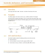
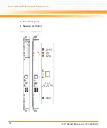
Base-IF and faceplate Ethernet activity can be seen through FPGA LEDs B1/U1, B2/U2 and U3.
3.2.2
Connectors
3.2.2.1
Faceplate Connectors
Hot Swap
Blue
FRU State Machine
During blade installation
–
Blue: Onboard IPMC powers up
–
Blue (blinking): Blade is communicating with the shelf manager
–
Off: Blade is active
During blade removal
–
Blue (blinking): Blade is notifying the shelf manager that it is
going to deactivate
–
Blue: Blade is ready to be extracted
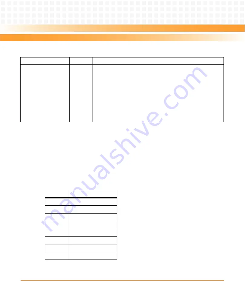
Table 3-1 Faceplate LEDs (continued)
Indicator
Color
Description
Table 3-2 RJ45 female Serial Line Connector Pinout
Pin
Signal
1
RTS
2
DTR
3
TXD
4
GND
5
GND
6
RXD
7
DSR
8
CTS
Содержание ATCA-7368
Страница 8: ...ATCA 7368 Installation and Use 6806800M12C Contents 8 Contents Contents ...
Страница 14: ...ATCA 7368 Installation and Use 6806800M12C 14 List of Figures ...
Страница 26: ...Introduction ATCA 7368 Installation and Use 6806800M12C 26 Figure 1 1 Declaration of Conformity ...
Страница 29: ...Introduction ATCA 7368 Installation and Use 6806800M12C 29 Figure 1 3 Mechanical Layout without AMC and HDD ...
Страница 30: ...Introduction ATCA 7368 Installation and Use 6806800M12C 30 Figure 1 4 Mechanical Layout without AMC with HDD ...
Страница 50: ...Hardware Preparation and Installation ATCA 7368 Installation and Use 6806800M12C 50 ...
Страница 88: ...Functional Description ATCA 7368 Installation and Use 6806800M12C 88 ...
Страница 210: ...Replacing the Battery ATCA 7368 Installation and Use 6806800M12C 210 ...
Страница 221: ......