


6
Model No.: ACF552
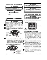
15.
Connect the ceiling fan wire connector to the
switch cup wire connector (Figure 9).
16.
Remove the M4 x 12mm flat head switch cup
cover screws (reserve for future use) (Figure 9).
NOTE: Make sure all wires and connector are
tucked under the switch cup and not pinched
between switch cup and switch cup cover.
17.
Position the switch cup onto the switch cup cover,
aligning each of the the three holes. Attach the
switch cup by reinstalling the three screw
previously removed in Step 15 (Figure 10).
M4 x 12mm FLAT
HEAD SCREW (3)
SWITCH CUP
SWITCH CUP
COVER
WIRE
CONNECTORS
Figure 9
SWITCH
CUP
M4 x 12mm FLAT
HEAD SCREW (3)
Figure 10
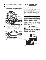
Electrical and Structural
Requirements
This new ceiling fan will require a grounded electrical
supply line of 240V, AC, 50Hz, 10 amp circuit.
If this fan is to replace an existing ceiling light
fixture,turn electricity off at the main fuse box at this
time and remove the existing light fixture.
The hanger bracket must be securely anchored and
capable of withstanding a load of at least 40kg.
Figure 11 depicts typical structural configuration that
may be used for securely mounting the fan.
Turning off wall switch is not sufficient. To avoid
possible electrical shock, be sure electricity is turned
off at the main fuse box before wiring. All wiring must
be in accordance with AS/NZS 3000 "the Wiring
Rules" and the ceiling fan must be properly grounded
as a precaution against possible electrical shock.
WARNING
Disconnect electrical supply and test before you
touch!
All wiring must be in accordance with AS/NZS 3000
“The Wiring Rules”.
The warranty on this fan will be void if the appliance is
not installed by a licensed electrician.
WARNING
The ceiling fan is 220-240V 50Hz Class I appliance
and will require an earth. Figure 11 depicts different
structural configurations that may be used for
securely mounting the fan.
CEILING
CEILING
JOISTS
50 x 200mm
TIMBER BATTEN
BETWEEN JOISTS
CEILING JOIST
Figure 11


