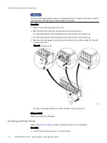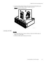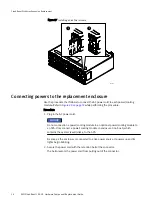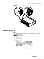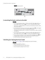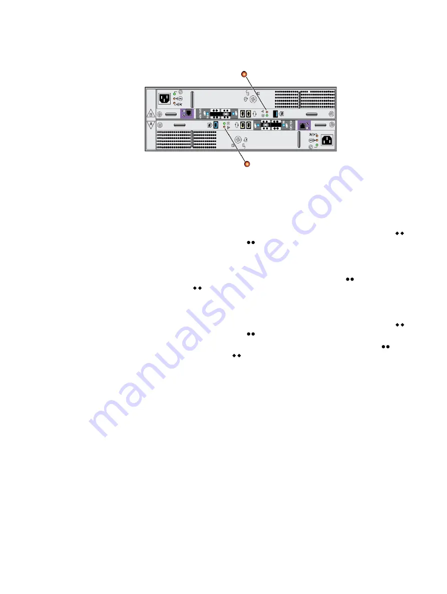
Figure 30 Enclosure fault LED
Connecting the back-end bus to the DAE
Procedure
1. On LCC A in the previous enclosure on the bus, locate the cable plugged into the
port and plug its free end into the port on LCC A in the replacement enclosure.
The enclosure immediately before an enclosure on the same back-end bus is called
the previous enclosure.
2. On LCC A in the next enclosure, locate the cable plugged into the port and plug its
free end into the port on LCC A in the replacement enclosure.
The enclosure immediately after an enclosure on the same back-end bus is called the
next enclosure.
3. On LCC B in the previous enclosure on the bus, locate the cable plugged into the
port and plug its free end into the port on LCC B in the replacement enclosure.
4. On LCC B in the next enclosure on the bus, locate the cable plugged into the port
and plug its free end into the port on LCC B in the replacement enclosure.
5. Verify that the Bus ID LED displays the expected value.
Installing and locking the front bezel
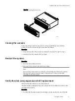
Refer to
while performing the procedure that follows.
Procedure
1. Align the bezel with the enclosure.
2. Gently push the bezel into place until it latches.
3. Secure the bezel by turning the key in the lock.
CloudBoost Disk Array Expansion Replacement
52
EMC CloudBoost 100
2.0
Hardware Component Replacement Guide
Содержание CloudBoost 100
Страница 1: ...EMC CloudBoost 100 Version 2 0 Hardware Component Replacement Guide P N 302 002 471 REV 02 ...
Страница 6: ...FIGURES 6 EMC CloudBoost 100 2 0 Hardware Component Replacement Guide ...
Страница 8: ...TABLES 8 EMC CloudBoost 100 2 0 Hardware Component Replacement Guide ...
Страница 14: ...CloudBoost 100 Overview 14 EMC CloudBoost 100 2 0 Hardware Component Replacement Guide ...
Страница 20: ...Disk Drive Replacement 20 EMC CloudBoost 100 2 0 Hardware Component Replacement Guide ...


