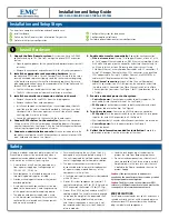
connecting Multiple Expansion Shelves
EMC DATA DOMAIN DD860 INSTALLATION AND SETUP GUIDE | SIDE 1
ExPanSion SHElF cablinG
Multiple expansion shelves are connected together and to the controller with
qualified SAS cables. The system may be configured with between one and
twelve expansion shelves. The order of connectivity does not matter. See
Figure 5 for the recommended cabling of a 12-shelf system configuration.
4
Use a SAS cable with an SFF-8088 (mini-SAS) connector to connect to
the SAS port on the controller and an SFF-8470 connector to connect to
the ES20.
4
Use a SAS cable with two SFF-8470 connectors to connect one ES20 to
another ES20.
4
Up to eight SAS ports are used for expansion shelf connections.
4
If you are connecting this system to shelves that had pre-existing cabling,
re-cable them to match the routing shown in this section.
NOTE:
The system supports any combination of 16 TB and 32 TB shelves, up to a
maximum of 12 shelves or 192 TB of raw storage.
IMPORTANT:
The SAS connectors must be secured with their screw lock assem-
blies to ensure the mechanical connection. It is important that the SAS cables be
properly dressed and supported using the included Velcro straps.
Hot aDDition oF ExPanSion SHElvES
The system supports the hot addition of expansion shelves. Use the instruc-
tions below to add expansion shelves.
4
Install each new expansion shelf following the instructions in the
Install
Hardware
section, steps 1, 2, and 3.
4
Odd-numbered shelves are installed below the DD860 system. Even-
numbered shelves are installed above the DD860 system.
adding ES20 Shelves
(See Figure 5)
4
First ES20:
Connect a SAS cable with a mini-SAS connector from control-
ler port 3A to the ES20 Controller A HOST port.
Connect a SAS cable with a mini-SAS connector from controller port 2B to
the ES20 Controller B HOST port.
4
Second ES20:
Connect a SAS cable with a mini-SAS connector from
controller port 2A to the ES20 #2 Controller A HOST port.
Connect a SAS cable with a mini-SAS connector from controller port 3B to
the ES20 #2 Controller B HOST port.
4
Third ES20:
Disconnect the SAS cable from Controller B HOST port on the
ES20 #1 and connect it to Controller B HOST port on ES20 #3.
Using a SAS cable with SFF-8470 connectors, connect Controller B EXP’N
port on ES20 #3 to Controller B HOST port on ES20 #1.
Using a SAS cable with SFF-8470 connectors, connect Controller A EXP’N
port on ES20 #1 to Controller A HOST port on the ES20 #3.
4
Fourth ES20:
Disconnect the SAS cable from Controller A Host port on
ES20 #2 and connect it to Controller A Host port on ES20 #4.
Using a SAS cable with SFF-8470 connectors, connect Controller B EXP’N
port on ES20 #2 to Controller B HOST port on ES20 #4.
Using a SAS cable with SFF-8470 connectors, connect Controller A EXP’N
port on ES20 #4 to Controller A HOST port on ES20 #2.
4
Fifth ES20:
Disconnect the SAS cable from Controller B HOST port on the
ES20 #3 and connect it to Controller B HOST port on ES20 #5.
Using a SAS cable with SFF-8470 connectors, connect Controller B EXP’N
port on ES20 #5 to Controller B HOST port on ES20 #3.
Using a SAS cable with SFF-8470 connectors, connect Controller A EXP’N
port on ES20 #3 to Controller A HOST port on the ES20 #5.
4
Sixth ES20:
Disconnect the SAS cable from Controller A Host port on
ES20 #4 and connect it to Controller A Host port on ES20 #6.
Using a SAS cable with SFF-8470 connectors, connect Controller A EXP’N
port on ES20 #6 to Controller A HOST port on ES20 #4.
Using a SAS cable with SFF-8470 connectors, connect Controller B EXP’N
port on ES20 #4 to Controller B HOST port on ES20 #6.
Remember to connect A ports to A ports and B ports to B ports.
Note:
For ports C and D, follow the same topology as described for ports A and B.
Power-up and Final configuration
4
Power on the expansion shelf or shelves using the instructions in the
Install Hardware
section.
4
Use the
disk add enclosure
command when ready to put the
enclosure into use and expand the capacity of the system. The enclosure-
id is always 2 for the first added shelf, and 3 for the second. The Data
Domain controller always has the enclosure-id of 1 (one).
disk add enclosure enclosure-id
FiGurE 5: rEcoMMEnDED ES20 cablinG DiaGraM
SAS Cable Routing for A side
4
A
side ES20 controller slots have yellow
labels
4
a
port on HBA always connects to
A
controller on ES20
• 2
c
A
side of top ES20 in set 4
• 3
c
A
side of top ES20 in set 3
• 2
a
A
side of top ES20 in set 2
• 3
a
A
side of top ES20 in set 1
4
A
side routes from the top down
SAS Cable Routing for B side
4
B
side ES20 controller slots have blue
labels
4
b
port on HBA always connects to
B
controller on ES20
• 2
b
B
side of bottom ES20 in set 1
• 3
b
B
side of bottom ES20 in set 2
• 2
d
B
side of bottom ES20 in set 3
• 3
d
B
side of bottom ES20 in set 4
4
B
side routes from the bottom up


